background image

Summary of Contents for 139.53535SRT1

Page 1: ...ns before first use of this product Fasten the manual near the garage door after installation Complies with UL 325 _11 _ regulations effective January I I993 1 2 P GARAGE DOO Safety Precautions Assembly installation Adjustment Care and Maintenance Operation Troubleshooting Parts List I RRFTSMRNo OPENE Sears Roebuck and Co Hoffman Estates IL 60179 U S A ...

Page 2: ...to trolley one piece door 27 Adjustment section pages 28 30 Travel limit adjustments 28 Force adjustments 29 Test the safety reversing sensor 30 Test the safety reverse system 30 Operation safety instructions 31 Care of your opener 31 Maintenance schedule 31 Operation of your opener 32 Receiver and remote control programming 33 Having a problem 34 35 Repair parts rail assembly 36 Repair parts inst...

Page 3: ...es left on a garage door could cause someone to become entangled and killed Remove all ropes connected to the door before installing and operating the opener Identify the type and height of your door and any special conditions that exist and any additional materials that may be required by referring to the lists on page 4 or page 5 To avoid damage to the garage door and opener disable locks before...

Page 4: ...ed to mounting locations before sensors are installed Step 10 page 22 Alternate floor mounting of the safety reversing sensor will require hardware not provided Step 11 page 24 Do you have a steel aluminum fiberglass or glass panel door If so horizontal and vertical reinforcement is required Look at the garage door where it meets the floor it must close on the floor all the way across Otherwise th...

Page 5: ... reversing sensor will require hardware that is not provided Step 11 page 25 Generally a one piece door does not require reinforcement If your door is lightweight you can refer to the information relating to sectional doors on page 24 Step 11 page 25 Depending on your door s construction you might need additional mounting hardware for the door bracket Do you have an access door in addition to the ...

Page 6: ...44 2 53647 1 Three Function Remote Control with Visor Clip 2 Conductor Bell Wire White White Red Sprocket Cover _ Trolley T Rail Cable T Ra Pulley Bracket __nd Sectione Header Bracket Door Bracket Safety Reversing Sensor Mounting Bracket With Square Holes 2 C Wrap 2 Light Lens 2 Hanging Brackets Curved Door Arm Section 2 Safety Reversing Sensors I I Safety Labels 1 Sending Eye and 1 Receiving Eye ...

Page 7: ...1 4 20x7 16 4 Installation Hardware 0 5 16 18x7 8 4 l E I I E I I I E I I I_ Lag Screw 5 16 18xl 7 8 2 Carriage Bolt 5 16 18x2 1 2 2 CIevis Pin 5 16 x2 3 4 1 Nut 5 16 18 6 Ring Fastener 3 Handle _ IIllllllllllllllllll Screw 6ABxl 2 o _ ol Clevis Pin 5 16 x1 1 4 1 Rail Grease Lock Washer 5 16 6 Dry Wall Anchors 2 Rope Clevis Pin Insulated 5 16 xl 1 StapIes 16 Hex Screw 1 4 20x1 1 2 2 Safety Reversi...

Page 8: ...ews I J Improper assembly can cause jerky trolley operation noise and or nuisance door reversals Right Wrong I T RAIL BACK TO OPENER T raii End Section 1 4 Lock Nut Brace If T rail is not assembled EXACTLY as shown trolley will not travel smoothly along length of rail or it will hit against the nuts Brace T rail Center Section Carriage Bolt 1 4 20xl 2 T rail End Section Hex Screws 5 16 18x7 8 Cabl...

Page 9: ... the cover For convenience put a support under the cable pulley bracket Remove the 2 5 16 18xl 2 washered screws mounted in the top of the opener Align the holes in the back section of the T rail with the holes in the opener Fasten the rail with the 2 washered screws previously removed Tighten securely Remember to use only these screws Any other screws will cause serious damage to the opener Inser...

Page 10: ...inue forward to the trolley threaded shaft Figure 3 Use the second master link to connect the chain to the flat end of the shaft Check to make sure the chain is not twisted Remove the screwdriver Master Link Clip On Spring i i Mast Link Cap Cable Loop _ Master Link CIip On Spring i Master Link Cap Flat End of Trotley Threaded Shaft Figure 3 Chain T rail Pin Notch Install Chain and Cable In This Di...

Page 11: ...install only on a properly balanced and lubricated garage door An improperly balanced door may not reverse and could result in severe injury or death Repairs to cables spring assemblies and other hardware must be made by a professional service person before installing opener 3 Disable all locks and remove all ropes connected to the garage door before installing the opener Ropes connected to a gara...

Page 12: ...ader wall above the door Remember you can fasten the header bracket within 2 feet of the left or right of the door center only if a torsion spring or center bearing plate is in the way or you can attach it to the ceiling refer to page 14 when clearance is minimal it may be mounted on the wall upside down if necessary to gain approximately 1 2 If you need to install the header bracket on a 2x4 on w...

Page 13: ...aveI One piece door without track jamb hardware Door Header Highest Point Wall of Travel T C3 One piece door without track pivot hardware Open your door to the highest point of travel as shown Measure the distance from the top of the door to the floor Subtract the actual height of the door Add 8 to the remainder See Example Close the door and draw an intersecting horizontal line on the header wall...

Page 14: ... 1 Highest Point of Travel of Garage Door Door Spring Garage __ Door Vertical Center Line The nait hote is for positioning only You must use lag screws to mount the header bracket Optional Wall Mounting Holes Hardware Shown Actual Size La s c 5 16 9xl 5 8 Fasten the Header Bracket to the Ceiling Extend the vertical guideline onto the ceiling as shown Center the bracket on the vertical mark no more...

Page 15: ...ll need help Have someone hold the opener securely on a temporary support to allow the T rail to clear the spring Position the cable pulley bracket against the header bracket Align the bracket holes and join with a clevis pin as shown Insert a ring fastener to secure Clevis Pin 5 16 x2 3 4 Ring Fastener Header Bracket b i Cable Pulley Bracket T rail _ Garage Door Temporary Support Hardware Shown A...

Page 16: ...ley when you raise the door pull down on the trolley release arm to disconnect the inner and outer sections The trolley can remain disconnected until Step 12 is completed Door 2x4 Laid Flat Trol__ _leeyrm With the door fully open and parallel to the floor measure the distance from the floor to the top of the door Using a stepladder as a support raise the opener to the same distance as the door fro...

Page 17: ...ts Attach one end of each bracket to a support with 5 16 xl 8 1 7 8 lag screws Fasten the opener to the hanging brackets with 5 16 18x7 8 screws lock washers and nuts Check to make sure the T rail is centered over the door or in line with the header bracket if the bracket is not centered above the door Remove the 2x4 Operate the door manually If the door hits the rail raise the header bracket Grea...

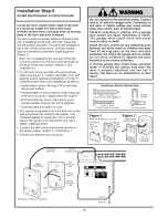
Page 18: ...ples to secure the wire in several places Be careful not to pierce the wire with a staple creating a short 4 Connect the bell wire to the terminal screws on the opener panel white to 2 white red to 1 5 Position the antenna wire as shown Do not connect to live electrical wiring Connect only to 24 Volt low voltage wires Connection to live wires or higher voltage may cause serious injury from shock b...

Page 19: ...r Adjustment Step 4 on page 30 Reverse the procedure to remove the lenses Lens Tab Lens f Tab Installation Step 8 Attach the Emergency Release Rope and Handle Thread one end of the rope through the hole in the top of the red handle so NOTICE reads right side up as shown Secure with an overhand knot The knot should be at least 1 from the end of the rope to prevent slipping Thread the other end of t...

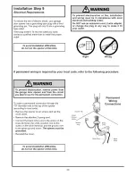
Page 20: ... adapter or change the plug in any way to make it fit your outlet Right Wrong if permanent wiring is required by your local code refer to the following procedure To make a permanent connection through the 7 8 diameter hole in the top of the opener according to local code Remove the opener cover screws and set the cover aside Remove the attached 3 prong cord Connect the black line wire to the screw...

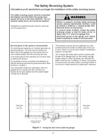
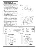
Page 21: ...er side of the garage door as long as the sun never shines directly into the receiving eye lens Look at the label on the connector end of each case to identify the sensors The brackets must be connected and fastened so that the sending and receiving eyes face each other as shown in Figure 1 If an obstruction breaks the light beam while the garage door is closing the door will stop and reverse to f...

Page 22: ... the floor but not exceeding 6 See warning on page 21 Attach bracket assemblies with 1 4 x1 1 2 lag screws as shown in Figure 3 Adjust right and left side bracket assemblies to the same distance out from the mounting surface Make sure all door hardware obstructions are cleared Tighten the nuts securely Figure 2 i ii 10 32 Lock Nuts Mounting Bracket With Square Holes J C Wrap 10 32x3 8 Screws Figur...

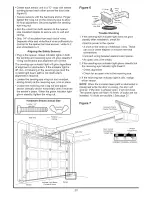
Page 23: ...g nut and adjust sensor vertically and or horizontally until it receives the sender s beam When the green indicator light glows steadily tighten the wing nut Figure 6 Indicator Light 1 4 20 x 1 1 2 Hex Bolt Trouble Shooting 1 If the sending eye indicator light does not glow steadily after installation check for Electric power to the opener A short in the white or white black wires These can occur ...

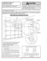
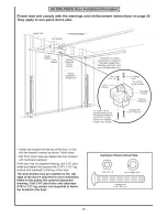
Page 24: ...glass aluminum steel doors with glass paneI etc Figure I Door Location Center the door bracket on the previously marked vertical guideline used for the header bracket installation Note correct UP placement as stamped inside the bracket Position the bracket on the face of the door within the following limits A The top edge of the bracket 2 4 below the top edge of the door B The top edge of the brac...

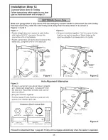
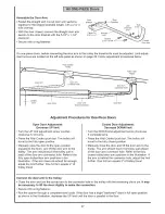
Page 25: ...onal installation use 5 16 x1 1 2 lag screws not supplied __ Carriage BoIt 5 16 18x2 1 2 Center the bracket on the top of the door in line with the header bracket as shown Mark holes Drill 5 16 pilot holes and fasten the door bracket with hardware supplied If the door has no exposed framing drill 3 16 pilot holes and fasten the bracket with 5 16 x1 1 2 lag screws not supplied to the top of the doo...

Page 26: ...holes that line up and join sections Select holes as far apart as possible to increase door arm rigidity inner Trolley r Outer Tro I I _1i C_evis Pin _0 Door I_ Straight 5c g _ _ _ _ DcoU Ar_ Figure 1 Door Bracket Emergency Release Handle Figure 2 Hole Alignment Alternative Figure 3 If holes in curved arm are above holes in straight arm disconnect straight arm Cut about 6 from the solid end Reconn...

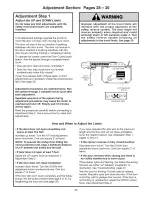
Page 27: ... the door arm to the trolley The arm should touch the trolley just in back of the door arm connector hole Refer to the fully open trolley door arm positions in the illustration If the arm does not extend far enough adjust the limit further One full turn equals 2 of trolley travel o o o Closed Door Adjustment Decrease DOWN limit Turn the DOWN limit adjustment screw clockwise 5 complete turns Press ...

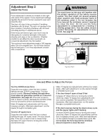
Page 28: ...erse system following all adjustments to the travel limits See page 30 Cover Protection Bolt I Limit Adjustment Screws Adjustment Label How and When to Adjust the Limits if the door does not open completely but opens at least five feet Increase up travel Turn the UP limit adjustment screw clockwise One turn equals 2 of travel NOTE To prevent the trolley from hitting the cover protection bolt keep ...

Page 29: ... Panel How and When to Adjust the Forces Test the DOWN close force Grasp the door bottom when the door is about halfway through DOWN close travel The door should reverse Reversal halfway through down travel does not guarantee reversal on a two inch obstruction See page 30 If the door is hard to hold or doesn t reverse decrease the DOWN close force by turning the control counterclockwise Make 10 de...

Page 30: ...esult in serious injury or death to persons trapped by a closing garage door Repeat this test once a month and adjust as needed GARAGE DOOR Important safety check Repeat Adjustment Steps 1 2 and 4 after Each adjustment of door arm length force controls or limit controls Any repair to or adjustment of the garage door including springs and hardware Any repair to or buckling of the garage floor Any r...

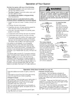
Page 31: ...moving the covers 8 SAVE THESE iNSTRUCTiONS Care of Your Opener Limit and force adjustment controls Limit Controls Adjustment Label Located on the left side panel Force Controls Adjustment Label Located on the right side paneI Weather conditions may cause some minor changes in door operation requiring some re adjustments particularly during the first year of operation Pages 28 and 29 refer to the ...

Page 32: ... use the emergency release rope and handle only when the door is fully closed ease Arm Trolley Emergency Release Handte Pult Down Manual disconnect position To open the door manually The door should be fully closed if possible Pull down on the red emergency release handle and lift the door manually To reconnect the door to the opener press the Door Control push button The lockout feature prevents ...

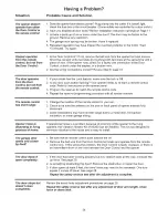
Page 33: ...ure 2 The opener lights will flash once 3 Release the remote push button Now the opener will operate when the remote control push button is pressed if you release the remote control push button before the opener lights flash the opener will not accept the code To Change the Selected Push Button On the Same Remote control If you decide to use a different remote control button than originally progra...

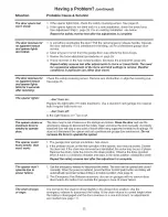
Page 34: ... control code 4 Repeat the receiver programming procedure with all remote controls The remote control 1 Change the location of the remote control in your car has short range 2 Check to be sure the antenna on the side or back panel of opener extends fully downward 3 Some installations may have shorter range due to a metal door foil backed insulation or metal garage siding Opener noise is If operati...

Page 35: ...ut of balance or the springs are broken Close the door and use the maximum force is emergency release to disconnect the trolley Open and close the door manually A properly needed to operate balanced door will stay in any point of travel while being supported entirely by its springs If it door does not disconnect the opener and call a professional garage door serviceman Do not increase the force to...

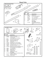
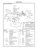
Page 36: ...4 16 12B485 17 12B350 18 178B34 41A3475 4 41A4116 114A1954 Premium control console 3 function remote control housing no circuit board 3V 2016 Lithium battery 2 required Visor clip for Part No 41A4873 Keyless entry keypad cover Keyless entry battery cover 12Volt battery Emergency rope handle assembly Header bracket w clevis pin fastener 2 conductor bell wire white white red Curved door arm section ...

Page 37: ...ear kit w grease Roll pins 2 Line cord Wire harness assembly w plug Receiver logic board assembly Complete with Logic board End panel w all labels End panel w all labels Light socket 9 108D48 2 Lens 10 30B363 Capacitor 1 2HP 11 12A373 Capacitor bracket 12 41A3150 Terminal block w screws 13 41D3058 Universal replacement motor bracket assembly Complete with Motor worm bracket bearing assembly RPM se...

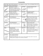
Page 38: ...d on garage construction Includes brackets and fastening hardware 139 53879 139 53859 139 53876 139 53774 139 53773 3 Function Remote Control Includes visor clip Compact 3 Function Remote Control With loop for attaching key ring Multi Function Keyless Entry Enables homeowner to operate garage door opener from outside by entering a 4 digit code on specially designed keypad Plug In Light Control Ena...

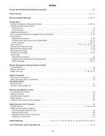
Page 39: ... 28 Problems that might require limit adjustments 34 35 Safety warnings 28 31 Manual Emergency Release Rope Handle Lockout featu re 32 Manual disconnect 32 Safety warnings 11 19 31 32 Opener Terminals Door control connections 18 Safety reversing sensor connections 23 Operational Noise Sprocket noise 11 Vibration noise isolator kit 34 Receiver and Remote Control Programming the receiver 33 Erasing ...

Page 40: ...placement parts for any defective parts free of charge You pay for labor LIMITED WARRANTY ON MOTOR After 1 year and through 5 years if the motor on this Garage Door Opener is defective Sears will furnish replacement motor free of charge You pay for labor LIMITATION ON LIABILITY SEARS WiLL NOT BE LIABLE FOR LOSS OR DAMAGE TO PROPERTY OR ANY INCIDENTAL OR CONSEQUENTIAL LOSS OR EXPENSE FROM PROPERTY ...

Reviews: