background image

page 4

5. Fan Assembly.

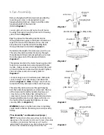
Remove hanging ball from downrod provided by 
loosening set screw on hanging ball. Lower 
hanging ball and remove stop pin and then slide 
hanging ball off of the downrod. 

[

Refer to 

diagram 1

.

]

Loosen yoke set screws and nuts at top of motor 
housing. Remove pin and clip from motor housing 
yoke. 

[

Refer to 

diagram 2

.

]

Tip

: To prepare for threading electrical wires 

through downrod, apply a small piece of electrical 
tape to the ends of the electrical wires--this will 
keep the wires together when threading them 
through the downrod. 

[

Refer to 

diagram 2

.

]

Determine the length of downrod you wish to use. 
Thread safety cable and electrical wires through 
threaded end of downrod and pull extra wire slack 
from the upper end of the downrod. 

[

Refer to 

diagram 2

.

Thread downrod into the motor housing yoke until 
holes for pin and clip in downrod align with holes 
in yoke--

make sure wires do not get twisted

. Re-insert 

pin and clip that were previously removed. Tighten 
yoke set screws and nuts securely. 

[

Refer to 

diagram 2

.

]

 
Locate canopy cover in hardware pack. Slide yoke 
cover, canopy cover and canopy over downrod.  

[

Refer to 

diagram 3

.

(

Note

: Canopy cover must be 

turned with shiny side 

toward

 the motor housing.)

Thread safety cable and wires through hanging 
ball; then slide hanging ball over downrod--the top 
of the downrod should be noted as having a set 
screw hole; use this hole when setting the set 
screw. Insert stop pin into top of downrod and raise 
hanging ball. Be sure stop pin aligns with slots on 
the inside of the hanging ball. Tighten set screw 
securely. 

[

Refer to 

diagram 4

.

]

WARNING

: Failure to tighten set screw completely 

could result in the fan becoming loose and possibly 
falling.  

["Fan Assembly"  continued on next page.]

NOTE

:  The important safety precautions and instructions 

appearing in the manual are not meant to cover all possible 
conditions and situations that may occur. It must be 
understood that common sense and caution are necessary 
factors in the installation and operation of this fan.

set screw

hanging ball

stop pin

diagram 2

diagram 1

diagram 3

diagram 4

canopy

motor
housing

yoke cover

canopy
cover

downrod

downrod

electrical wiring

safety cable

yoke set
screw 
and nut

pin

clip

set screw hole

hanging

 ball

stop pin

Summary of Contents for AT52

Page 1: ... 3 Fan Assembly pgs 4 5 Wiring pg 5 Canopy Assembly pg 6 Blade Assembly pg 6 Switch Housing Assembly pg 7 Testing Your Fan pg 7 Light Kit Assembly Optional pg 8 Troubleshooting pg 9 Parts Replacement pg 9 Warranty pg 9 sold separately net weight of fan 7 4 lb 16 31 kg PRINTED IN CHINA READ THESE INSTRUCTIONS AND SAVE THEM FOR FUTURE USE F P O F P O For Placement Only For Placement Only E192641 ...

Page 2: ...han 12 gauge or there is more than one house wire to connect to the corresponding fan lead wires consult an electrician for the proper size wire connectors to use 5 Electrical diagrams are for reference only Light kits that are not packed with the fan must be CUL Canada or UL USA listed and marked suitable for use with the model fan you are installing Switches must be CUL Canada or UL USA general ...

Page 3: ...inst parts inventory that all parts have been included 2 Parts Inventory a canopy 1 piece b hanging bracket 1 piece c 6in downrod and hanging ball 1 piece d 2in downrod 1 piece e motor housing 1 piece f yoke cover 1 piece g blade arm 5 pieces h switch housing 1 piece i blade 5 pieces j hardware packs Blade arm drawings in this manual are representative only a e f h b c IMPORTANT REMINDER You must ...

Page 4: ...utlet box be sure the outlet box is securely attached to the building structure and can support the full weight of the fan Ensure outlet box is clearly marked Suitable for Fan Support If not it must be replaced with an approved outlet box Failure to do so can result in serious injury CAUTION Be sure outlet box is grounded properly and that a ground wire GREEN or bare is present Install hanging bra...

Page 5: ...am 2 Locate canopy cover in hardware pack Slide yoke cover canopy cover and canopy over downrod Refer to diagram 3 Note Canopy cover must be turned with shiny side toward the motor housing Thread safety cable and wires through hanging ball then slide hanging ball over downrod the top of the downrod should be noted as having a set screw hole use this hole when setting the set screw Insert stop pin ...

Page 6: ... fan you are now ready to hang your fan Grab the fan firmly with two hands Slide downrod through opening in hanging bracket and let hanging ball rest on the hanging bracket Turn the hanging ball slot until it lines up with the hanging bracket tab WARNING Failure to align slot in hanging ball with tab in hanging bracket may result in serious injury or death Tip Seek the help of another person to ho...

Page 7: ...c motor lock Time Saver Washers for blade screws can be set on each blade screw prior to installing blades Locate 15 blade attachment screws and washers in hardware pack Hold blade arm up to blade and align holes Insert 3 blade attachment screws along with washers with fingers first and then tighten screws securely with a Phillips screwdriver Repeat for the remaining blades Remove blade arm screws...

Page 8: ...ling fan will allow you to raise your thermostat setting in summer and lower your thermostat setting in winter without feeling a difference in your comfort Important Reverse switch must be set either completely to the LEFT or completely to the RIGHT for fan to function If the reverse switch is set in the middle position diagram 4 fan will not operate Attach pull chain extension supplied or custom ...

Page 9: ...o male plug from motor housing matching up the colors on the male plug with the colors on the female plug for correct fit Make sure plugs connect completely Align holes in switch housing with holes in switch housing plate Re insert screws that were previously removed and securely tighten all 3 screws Attach glass shade s to light kit fitter using the hardware provided with the light kit Refer to d...

Page 10: ...IME WARRANTY CRAFTMADE ELLINGTON warrants this fan to the original household purchaser for indoor use under the following provisions 1 YEAR WARRANTY CRAFTMADE ELLINGTON will replace or repair any fan which has faulty performance due to a defect in material or workmanship Contact Craftmade Ellington Customer Service at 1 800 486 4892 to arrange for return of fan Return fan shipping prepaid to Craft...

Page 11: ...léctrica Pág 5 Colocación de la cubierta decorativa Pág 6 Colocación de las aspas Pág 6 Instalación de la caja de encendido Pág 7 Verificación del funcionamiento del ventilador Pág 7 Instalación del juego de luz opcional Pág 8 Localización de fallas Pág 9 Piezas de repuesto Pág 9 Garantía Pág 9 a la venta por separado peso neto del ventilador 7 4 kg 16 31 lb IMPRESO EN CHINA LEER ESTAS INSTRUCCION...

Page 12: ...libre del cable de la casa es superior al 12 o hay más de un cable de la casa para conectar a los cables principales del ventilador al cual corresponda cada uno consultar con un electricista para informarse sobre el tamaño correcto de conectores para cable que se debe usar 5 Los diagramas eléctricos son únicamente para referencia Los juegos de luz que no se incluyen con el ventilador deben tener e...

Page 13: ... para el aspa en este manual son representativos unicamente página 2 a Abrir el empaque cuidadosamente Sacar los artículos del embalaje Sacar el motor y ponerlo en una alfombra o en el embalaje para evitar rayar el acabado Guardar la caja de cartón o el empaquetamiento original en caso de que tenga que mandar el ventilador para alguna reparación Comprobar las piezas del ventilador con el inventari...

Page 14: ... 2 13m 7 pies 76cm 30 pulg Apagar los cortacircuitos en el panel de electricidad que suplen corriente a la caja de salida y asegurarse de que el interruptor de luz esté APAGADO ADVERTENCIA El no desconectar el suministro de fuerza antes de la instalación puede tener por resultado lesiones graves Quitar el aparato existente ADVERTENCIA Si utiliza una caja de salida existente asegurarse de que la ca...

Page 15: ... del cuello la tapa de la cubierta decorativa y la cubierta decorativa por el tubo Referirse al diagrama 3 Nota Se tiene que voltear la tapa de la cubierta decorativa para que el lado brillante dé al bastidor del motor Pasar los cables y el cable de seguridad por la bola que sirve para colgar luego deslizar la bola que sirve para colgar sobre el tubo la parte de arriba del tubo debe tener el aguje...

Page 16: ...e del cable de seguridad bastidor del motor ranura en la bola que sirve para colgar 6 Instalación eléctrica PRECAUCION Asegurarse de que la caja de salida esté conectada a tierra como es debido y que exista un conductor a tierra VERDE o pelado Asegurarse de que toda conexión eléctrica cumpla con los Códigos o las Ordenanzas Locales y el Código Nacional Eléctrico Si usted no está familiarizado con ...

Page 17: ...Para ahorrar tiempo Se pueden poner las arandelas en los tornillos que son para las aspas antes de colocar las aspas Localizar 15 tornillos para fijar las aspas y 15 arandelas en uno de los paquetes de artículos de ferretería Agarrar uno de los brazos para las aspas y juntarlo con una de las aspas para alinear los agujeros Introducir 3 tornillos para fijar las aspas junto con las arandelas con los...

Page 18: ...ición DERECHA en invierno diagrama 3 Un ventilador de techo le permitirá subir el termostato en verano y bajarlo en invierno sin notar una diferencia en su comodidad Importante Hay que mover el interruptor de reversa o completamente hacia la IZQUIERDA o completamente hacia la DERECHA para que funcione el ventilador Si el interruptor de reversa está puesto en la posición de en medio diagrama 4 no f...

Page 19: ...hufe macho del bastidor del motor al enchufe hembra de la caja de encendido haciendo coincidir los colores en el enchufe macho con los del enchufe hembra para que se encajen Asegurarse de que se conecten bien los enchufes Alinear los agujeros en la caja de encendido con los agujeros en la placa de la caja de encendido Volver a introducir los tornillos que se quitaron anteriormente y apretar bien l...

Page 20: ... de hacer localización de fallas para cualquier problema de instalación eléctrica puede causar lesiones graves GARANTIA LIMITADA DE POR VIDA DE CRAFTMADE ELLINGTON CRAFTMADE ELLINGTON garantiza este ventilador al comprador original de grupo familiar para uso interior con las siguientes condiciones GARANTIA DE 1 AÑO CRAFTMADE ELLINGTON reemplazará o reparará cualquier ventilador que tenga funcionam...

Reviews: