background image


17

BLADE TENSION


A properly tensioned blade is very 
important to get the best performance from 
any band saw. If the blade is too loose 
there is a possibility that the blade will slip 
or drift off the line while in operation and it 
will be hard to have accuracy in the line of 
cut. If the blade is tensioned too tightly, it 
will be very difficult to make tighter radius 
cuts and there will be a great possibility of 
blade breakage. When using a wider blade 
for making straight cuts, for re-sawing or 
making wide radius cuts, tighter blade 
tension is recommended; while using 
narrower blades for cutting shorter stock or 
making tighter radius cuts, less blade 
tension is recommended. 


BLADE TENSION ADJUSTMENT 


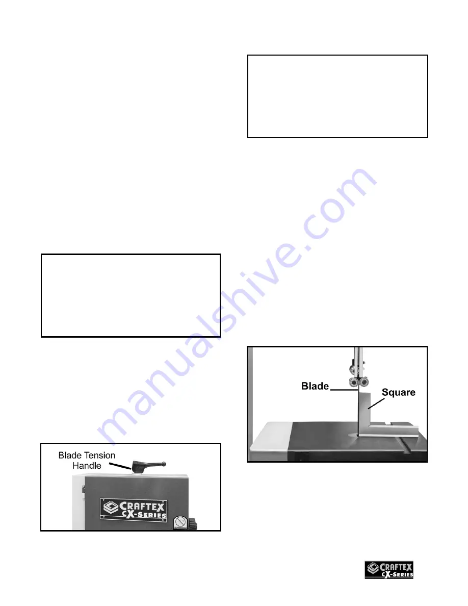
To adjust the blade tension, turn the blade 
tension handle shown in figure-27 
clockwise to increase the blade tension and 
counter-clockwise to decrease it. 
 
To release tension simple lift the handle up. 


Figure-27 Blade tension adjustment 


TABLE ADJUSTMENT 


CX104 features a table stop which allows 
the table to easily come to 90° if the table is 
tilted. 
 
To adjust the table stop so that the table 
sits at 90°, you should first make sure the 
switch is in “OFF” position and the power 
cord is unplugged. 
 
Loosen the two table lock knobs under the 
table. 
 
Place a square on the table as shown in 
figure-28. 


Figure-28 Table adjustment 

 
Loosen the lock nut on the table stop bolt 
and thread the table stop bolt in or out so 
that the square is touching the table and the 
blade with its full length and the table is at a 
90° with the blade. 


IMPORTANT 

The information above is just a guideline 
for you to understand to set the blade 
tension according to the cut. However, 
understanding the blade tension 
adjustment comes with practice. 


IMPORTANT 

To prolong the life of the blade and 
reduce blade stretching, when the 
machine is not in use for period of 24 
hours or more release the tension on the 
blade. 

Summary of Contents for CX104

Page 1: ...CX104 14 WOOD BAND SAW User Manual ...

Page 2: ...peed Change Settings 15 Support Bearing Adjustments 15 Blade Tension 17 Table Adjustment 17 Table Tilt Scale 18 Table Alignment 18 ON OFF Switch 19 Work piece Inspection Wood 19 Operations 20 Ripping 20 Cross Cutting 20 Re Sawing 21 Cutting Curves 21 Maintenance 22 Removing Installing Blade 22 Cleaning and Lubrication 23 V Belt 23 Removing Replacing the V Belt 23 CX104 Optional Accessories 24 Part...

Page 3: ... ENVIRONMENT is important Keep the area free of dust dirt and other debris in the immediate vicinity of your machine BE ALERT DO NOT use prescription or other drugs that may affect your ability or judgment to safely use your machine DISCONNECT the power source when changing blade and or making adjustments NEVER leave a tool unattended while it is in operation NEVER reach over the table when the to...

Page 4: ...the OFF position and the cord is un plugged from the power source NEVER LEAVE the band saw unattended while it is running DO NOT attempt to remove jammed pieces unless the band saw has come to a complete stop and the power switch has been turned to the OFF position NEVER TURN ON the band saw if the blade is in contact with your stock ALWAYS ENSURE that the guide blocks are properly set to prevent ...

Page 5: ...ered to Motor 1 HP 110 V Single Phase Switch ON OFF Switch 2 Speeds 2300 3200 FPM Cast Iron Table Size 14 x 18 Including Extension Table Table Tilt 5 to 45 Wheel Construction Precision Balanced Cast Iron Max Blade Width 3 4 Min Blade Width 1 8 Maximum Cutting Height 7 Floor to Table Height 44 Cutting Capacity Throat 13 5 8 Dust Collection Port 4 Blade Length 101 Bearings Sealed and Permanently Lub...

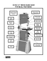
Page 6: ...n Handle Upper Cabinet Lock Knob Blade Guide Lock Knob Blade Guide Blade Guard Miter Gauge Table Trunnion Lock Knob Dust Port Stand Extension Table ON OFF Switch Powder Coated Paint Lower Cabinet Lock Knob Lower Cabinet Upper Cabinet Cast Iron Table Blade Guide Bearings ...

Page 7: ...e Insert 1 M Table Trunnion Lock Knobs 2 N Stop Paddle 1 O Table Stop Bolt 1 P Rubber Feet for Stand 4 Q Hardware Bag s 2 SETUP The unpainted surface of the table is coated with a rust preventive waxy oil and you will want to remove this before you begin assembly Use a solvent cleaner that will not damage painted surfaces When setting up your machine you will want to find an ideal spot where your ...

Page 8: ...3 prong grounded receptacle as shown in figure 3 Do not remove the grounding prong to fit it into a 2 pronged outlet Figure 3 110 Volts outlet for CX104 It is strongly recommended not to use extension cords with your CX104 Always try to position your machine close to the power source so that you do not need to use extension cords In case if you really find it necessary to use an extension cord mak...

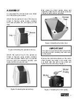
Page 9: ...s and the legs are attached properly and tighten all the screws and nuts Figure 5 Installing the second leg Now place the stand upside down and install the rubber feet to the stand as shown in figure 6 using screws provided Figure 6 Installing the rubber feet Remove the protective plastic on the motor shaft Position the pulley on the shaft until it is flush with the end of the shaft and tighten th...

Page 10: ...washers and tighten the nuts provided onto the carriage bolts Do not fully tighten the nuts at this time Figure 9 Mounting the motor Place the stand and the band saw upright Get the help of a friend or assistant and lift the machine and place it on the stand Align the mounting holes on the machine with the holes on the stand and secure the machine on to the stand using washers and bolts provided S...

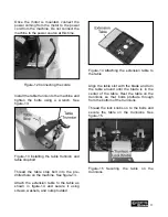
Page 11: ...p bolt into the pre drilled hole on the machine See figure 13 Attach the extension table to the table as shown in figure 14 and secure it using screws washers and nuts provided Figure 14 Attaching the extension table to the table Align the table slot with the blade and turn the table around until the blade is in the center of the table Rest the table on the trunnions so that bolts protrude through...

Page 12: ... tracking can be controlled by adjusting the upper wheel tilt lock knob See figure 18 TO CHECK AND ADJUST THE BLADE TRACKING Disconnect the machine from the power source and open the upper wheel cover Rotate the upper wheel by hand slowly and see how the blade rides on the wheel If the blade is not properly aligned and needs to be adjusted loosen the lock nut shown in figure 18 and turn the knob I...

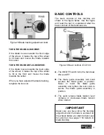
Page 13: ...f this machine are shown in the figure below Use the figure and read the text to understand what the basic controls of this band saw are Figure 19 Basic controls of CX104 A The ON OFF switch turns the band saw ON and OFF B The blade guide assembly lock knob secures the blade guide in position Raise or lower the blade guide assembly and tighten the lock knob to secure the blade guide assembly in po...

Page 14: ... use the proper sized hose and make sure all the connections are sealed tightly It is recommended to use a proper sized dust collector with CX104 to ensure adequate dust collection Figure 20 Dust port Before starting the band saw make sure that you have read and understood the manual and you are familiar with the functions and safety features on this machine Failure to do so may cause serious pers...

Page 15: ...200 FPM line up the drive belt on the first step of the pulleys See figure 22 Once you have positioned the drive belt on the pulleys retighten the motor mounting nuts securing the motor in position Figure 22 Belt positions for speed change SUPPORT BEARINGS ADJUSTMENT The guide bearings beside and thrust bearing behind the blade support the blade to move in a straight line during cutting operation ...

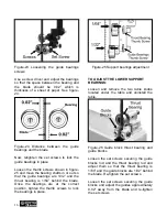
Page 16: ... 1 64 behind the blade Once the bearings are at the correct position tighten the thumb screws to lock the bearings in place Figure 25 Support bearings adjustment TO ADJUST THE LOWER SUPPORT BEARINGS Loosen and remove the two table knobs located under the table and uninstall the table Figure 26 Guide block thrust bearing and guide blocks Loosen the set screws securing the guide blocks rod and the t...

Page 17: ...ise to decrease it To release tension simple lift the handle up Figure 27 Blade tension adjustment TABLE ADJUSTMENT CX104 features a table stop which allows the table to easily come to 90 if the table is tilted To adjust the table stop so that the table sits at 90 you should first make sure the switch is in OFF position and the power cord is unplugged Loosen the two table lock knobs under the tabl...

Page 18: ...table should be aligned properly with the blade TO ALIGN THE TABLE Make sure the blade tension and tracking is done correctly Disconnect the machine from the power source and loosen the table lock knobs under the table Place a straightedge on the table so that the straightedge touches the blade and is parallel to it as shown in figure 31 Make sure the straight edge touches only the flat part of th...

Page 19: ... of these objects and it comes in contact with the blade the object might fly and hit the operator or seriously damage the blade For safety always inspect your work piece carefully before cutting and wear eye protection Some woods with excessive twisting or wrapping are un stable while cutting and are dangerous to cut because during operation the work piece can move un expectedly which can either ...

Page 20: ...CROSSCUTTING Cutting solid wood across the grain and in plywood or metal cutting across the width of the work piece is called crosscutting Mark the work piece where you want to start the cut from and make sure the miter gauge is at 90 position on the miter slot Place the work piece on the table so that the marked point is aligned with the blade and hold the work piece against the miter gauge Turn ...

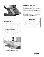
Page 21: ...ade is completely through the work piece Figure 35 Resawing on CX104 CUTTING CURVES For cutting curves always try to use narrower blades When cutting curves feed the stock into the blade and turn it very carefully so that the blade follows the line of cut and make sure the blade does not twist Make relief cuts through the waste part of the work piece which makes the job easier and prevents the bla...

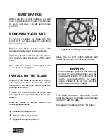
Page 22: ...on the table so that the teeth of the blade are pointing downwards Position the blade through the upper and lower guide bearings and install it over the wheels Once the blade is installed perform the following adjustments Bade tension adjustment Blade tracking adjustment Support bearings adjustment Figure 36 Installing the new blade Close the top and bottom cabinets and install the table pin and t...

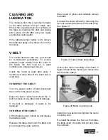
Page 23: ...PECT THE V BELT Turn the power switch off and disconnect the cord from the power source Open the lower cabinet and check the V belt for cracks or any other kind of damage If the belt is damaged it needs to be replaced TO REPLACE THE V BELT Lift the blade tension handle up and release the blade tension Remove the table insert and the table lock pin and open the upper cabinet Wear a pair of gloves a...

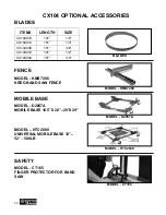
Page 24: ...2 CX104034 101 3 4 FENCE MODEL KMS7200 KREG BAND SAW FENCE MOBILE BASE MODEL D2057A MOBILE BASE 18 5 X 20 29 X29 MODEL HTC2000 UNIVERSAL MOBILE BASE 12 52 500LB SAFETY MODEL CT165 FINGER PROTECTOR FOR BAND SAW BLADES MODEL KMS7200 MODEL D2057A MODEL HTC2000 MODEL CT165 CX104 OPTIONAL ACCESSORIES ...

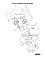
Page 25: ...25 CX104 BODY PARTS BREAKDOWN ...

Page 26: ... LOCK WAWHER 5 16 115 LOCK NUT M8 P1 25 145 PIN 6 16mm 116 UPPER WHEEL BASE 146 GUARD LOCKING KNOB 117 UPPER WHEEL BASE 147 PHILLIPS HEAD SCREW 1 4 3 4 118 Upper Wheel Cast Iron 148 STRAIN RELIEF 119 C RING R35 149 KNOB BOLT5 16 1 120 BEARING 6202ZZ2 150 CORD 121 FLAT WASHER 1 4 16 1 2mm 151 CORD 122 TIRE 152 CORD 123 BLADE 0 65 10 6T 101 153 WASHER 3 16 124 LOCK WASHER 1 4 154 HEX NUT 3 16 125 UP...

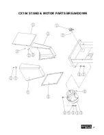
Page 27: ...27 CX104 STAND MOTOR PARTS BREAKDOWN ...

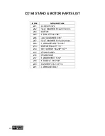
Page 28: ...EX NUT 5 16 18P 206 LOCK WASHER 5 16 207 FLAT WASHER 5 16 20 2 0mm 208 CARRIAGE BOLT 5 16 1 213 MOTOR PULLEY 15 214 SET SCREW 1 4 20P 1 4 215 STAND PANEL 216 STAND SIDE 217 RUBBER FEET 5 16 218 HEX BOLT 5 16 3 4 220 WASHER 5 16 16 8 16 221 CARRIAGE BOLT CX104 STAND MOTOR PARTS LIST ...

Page 29: ...29 CX104 TABLE PARTS BREAKDOWN ...

Page 30: ...RED PIN0 6 38MM 329 POINTER 310 HEX BOLT 3 8 2 330 PHILLIPS H D SCREW 3 16 1 4 311 TRUNNION CLAMPSHOE 331 SUPPORT BRACKET LOWER 312 TRUNNION 332 MITER GAUGE 19m m T 313 HEX BOLT 1 4 20P 3 4 333 BEARING SHAFT 314 HEX BOLT 1 4 20P 3 4 334 SUPPORT 315 SET SCREW 1 4 20P 1 4 335 EXTENSION TABLE 316 TABLE BRACKET 336 HEX BOLT 1 4 20P 3 4 317 LOCK KNOB F TABLE 3 8 40 318 SUPPORT BRACKET 7 8ID 319 HEX SHA...

Page 31: ...er handy All returned merchandise will be subject to a minimum charge of 15 for re stocking and handling with the following qualifications Returns must be pre authorized by us in writing We do not accept collect shipments Items returned for warranty purposes must be insured and shipped pre paid to the nearest warehouse Returns must be accompanied with a copy of your original invoice as proof of pu...

Reviews: