background image


20 

OPERATIONS 


Before operating the band saw make sure 
you have performed the following 
adjustments: 
 

  Blade tension adjustment 
  Blade tracking adjustment  
  Guide bearings adjustment 
  Make sure all the guards are in place 


Ripping 

 
Cutting solid wood with the grain cutting 
down the length of the work-piece is called 
ripping. 
 
Adjust the fence on the rails, according to 
the width of the cut on the work-piece and 
turn the hand-wheel to set the guide post 
assembly 1” above the work-piece.  
 
Now, turn the band saw ON and use a push 
stick or the band saw finger protector model 
CT165 (See page-24) to push the work-
piece against the blade. See figure-30 


Figure-30 Ripping on CX101 


Crosscutting 

 
Cutting solid wood across the grain and in 
plywood or metal cutting across the width of 
the work-piece is called crosscutting. 
 
Mark the work-piece where you want to 
start the cut from and make sure the miter 
gauge is at 90° position on the miter slot. 
Place the work-piece on the table so that 
the marked point is aligned with the blade 
and hold the work-piece against the miter 
gauge. 
 
Turn the band saw ON and feed the work-
piece against the blade. See figure-31 


Figure-31 Crosscutting on CX101 


WARNING 


CX101 produces fine dust particles 
during cutting operation which is very 
dangerous for health. Always connect 
your band saw to a dust collector. 


WARNING 

 
Do not use your fingers to feed narrow 
work-pieces into the blade. If you slip, 
your fingers might come close the blade. 
Always use a push stick. 


Summary of Contents for CX101

Page 1: ...CX101 18 VARIABLE SPEED WOOD METAL BAND SAW User Manual ...

Page 2: ...15 Table Tilt Scale Calibration 16 Table Alignment 16 Guide Post 17 Work Piece Inspection 17 Work Piece Inspection Metal 18 Blade Selection Metal 18 Cast Iron Wheels 19 Coplanar Adjustment 19 Operations 20 Ripping 20 Cross Cutting 20 Re Sawing 21 Cutting Curves 21 Connecting to a Dust Collector 21 Maintenance 22 Removing Installing Blade 22 Blade Table Alignments 22 Tilting the table Backward 23 T...

Page 3: ... ENVIRONMENT is important Keep the area free of dust dirt and other debris in the immediate vicinity of your machine BE ALERT DO NOT use prescription or other drugs that may affect your ability or judgment to safely use your machine DISCONNECT the power source when changing blade and or making adjustments NEVER leave a tool unattended while it is in operation NEVER reach over the table when the to...

Page 4: ...the OFF position and the cord is un plugged from the power source NEVER LEAVE the band saw unattended while it is running DO NOT attempt to remove jammed pieces unless the band saw has come to a complete stop and the power switch has been turned to the OFF position NEVER TURN ON the band saw if the blade is in contact with your stock ALWAYS ENSURE that the guide blocks are properly set to prevent ...

Page 5: ...uld be adhered to Motor 1 5 HP 220V Single Phase Switch On Off Paddle Variable Speed 150 3000 FPM Cast Iron Table Size 18 x 24 Table Tilt 0 to 10 Left and 0 to 45 Right Wheel 18 Max Blade Width 1 8 Min Blade Width 1 3 4 Maximum Cutting Height 12 Floor to Table Height 37 1 4 Cutting Capacity Throat 17 1 2 Dust Collection Ports 2 Ports 4 Blade Length 133 Bearings Sealed and Permanently Lubricated Co...

Page 6: ...le Upper Cabinet Lock Knob Blade Guide Adjustment Hand Wheel Blade Guide Lock Knob Blade Guard Miter Gauge Rear Fence Rail Front Fence Rail Lower Cabinet Lock Knob Base Table Fence On Off Switch Powder Coated Paint Fence Cam Lock Handle Variable Speed Control Digital Display One Piece Construction ...

Page 7: ...ine is in good condition The hardware screws washers etc might be shipped in a plastic bag After the machine has been un packed check that all loose parts and hardware are present List of Contents A Table 1 B Table Insert 1 C Table Lock Knobs 2 D Extension Table 1 E Table Pin 1 F Allen Keys 2 G Wrench 1 Figure 1 Inventory List of Contents H Miter Gauge Holder 1 I Fence Holder 1 J Miter Gauge 1 K S...

Page 8: ... adaptor plug is used it must be attached to the metal screw of the receptacle Figure 3 220 Volts Outlet for CX101 It is strongly recommended not to use extension cords with your CX101 Always try to position your machine close to the power source so that you do not need to use extension cords In case if you really find it necessary to use an extension cord make sure the extension cord does not exc...

Page 9: ... extension table Now turn the table up right and remove the table pin from the table slot and the table insert if already installed and move the table in position around the blade guiding through the table slot See figure 6 Figure 6 Installing the table Position the table on the base in such a way that the bolts under the table extend through the holes on the base Thread the two knobs on the bolts...

Page 10: ...igure 10 Figure 10 Rear rail brackets attached Now attach the rear rail to the brackets using the knobs provided See figure 11 Figure 11 Installing the rear fence rail Take the rail brackets larger for the front fence rail and attach it to the table using the cap screws provided Place the front fence rail on the brackets and insert the knobs through the hole on each bracket and thread the T nuts o...

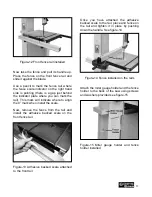
Page 11: ...align the 0 mark when install the scale Now remove the fence from the rail and install the adhesive backed scale on the front fence rail Figure 13 Adhesive backed scale attached to the front rail Once you have attached the adhesive backed scale to the rail place and fence on the rail and tighten it in place by pushing down the handle See figure 14 Figure 14 Fence installed on the rails Attach the ...

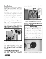
Page 12: ...obs clockwise If the blade moves towards the front edge of the wheel It makes the top of the wheel to tilt back and moves the blade towards the center Turn the knobs counter clockwise If the blade moves towards the back edge of the wheel It makes the top of the wheel to tilt to the front and moves the blade towards the center Figure 17 Blade centered on the wheel When you have adjusted the blade t...

Page 13: ...ny unusual noise coming from the machine or the machine vibrates strangely stop the machine immediately and disconnect from the power source and investigate if you can find out the problem with your machine Before starting the band saw make sure that you have read and understood the manual and you are familiar with the functions and safety features on this machine Failure to do so may cause seriou...

Page 14: ... the ideal blade tension adjustment according to the width of the blade Figure 20 Quick release blade tension handle and scale Adjusting the Blade Tension To adjust the blade tension lift the blade tension handle shown in figure 20 and turn it Turning the handle clockwise will tighten the tension on the blade while turning the handle counter clockwise will loosen the blade tension Guide Bearings A...

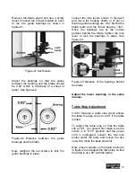
Page 15: ...blade teeth and the thrust bearing 1 64 Once the bearings are at the correct position behind the blade tighten the lock lever to lock the bearings in place See figure 23 Figure 23 Distance of the bearings behind the blade Adjust the lower bearings in the same manner Table Stop Adjustment CX101 features a table stop which allows the table to easily come to a 90 if the table is tilted To adjust the ...

Page 16: ...ment To make accurate cuts with your band saw the table should be aligned properly with the blade To align the table Make sure the blade tension and tracking is done correctly Disconnect the machine from the power source and loosen the two knobs under the table Place a straightedge on the table so that the straightedge touches the blade and is parallel to it as shown in figure 26 Make sure the str...

Page 17: ...to come on contact with the blade If the wood contains any of these objects and it comes in contact with the blade the object might fly and hit the operator or seriously damage the blade For a safe cutting method always inspect your work piece carefully before cut and wear eye protection Some woods with excessive twisting or wrapping are un stable while cutting and are dangerous to cut because dur...

Page 18: ...be cut using a vertical band saw Some hard metals take a longer time when cutting These kinds of metals need a different type of blade and lubrication while cutting Tanks cylinders valves that contain gasses or liquids can cause fire explosion or serious personal injury and damage to the machine Sometimes it is not safe to cut magnesium Cutting magnesium with a dull blade can create enough frictio...

Page 19: ...re power accuracy and less wandering This will be noticed most when it comes to resawing and making straight cuts with blades larger than 1 4 Coplanar Adjustment Figure 28 and Figure 29 show the shim for adjusting the top wheel To move the wheel out remove the nut and shims then remove the wheel Now you can add shims to the back of the wheels as required Replace the wheel and any remaining shims a...

Page 20: ...0 Figure 30 Ripping on CX101 Crosscutting Cutting solid wood across the grain and in plywood or metal cutting across the width of the work piece is called crosscutting Mark the work piece where you want to start the cut from and make sure the miter gauge is at 90 position on the miter slot Place the work piece on the table so that the marked point is aligned with the blade and hold the work piece ...

Page 21: ...rves feed the stock into the blade and turn it very carefully so that the blade follows the line of cut and make sure the blade does not twist Make relief cuts through the waste part of the work piece which makes the job easier and prevents the blade from twisting CONNECTING TO A DUST COLLECTOR CX101 features two 4 diameter dust ports to connect to a dust collector When connecting to a dust collec...

Page 22: ...h of the blade are pointing downwards Position the blade through the upper and lower guide bearings and install it over the wheels Adjust the blade tracking See page 12 and adjust the guide bearings See page 14 Once the blade is in the proper position turn the tension lever to tension the blade Figure 34 Installing the new blade Close the top and bottom cabinets and insert the table pin and table ...

Page 23: ...be re tensioned periodically To ensure optimum power transfer from the motor to the blade the belt must be in good condition and under proper tension Check the V belts at least after every 3 months and more often if the band saw is used daily To Inspect the V Belts 1 Turn the power switch off and disconnect the cord from the power source 2 Lift the blade tension handle up and release the tension 3...

Page 24: ...p pressure on the idler pulley and tighten the mounting nut 11 Check the wheel pulley V belt if tensioned properly If tension is necessary pivot the motor to tighten the motor V belt Keep pressure on the motor and tighten the motor adjustment bolt 12 Check the motor V belt if properly tensioned and tighten the motor hinge bolt 13 Install back the wheel blade and close the cabinets WARNING When ins...

Page 25: ...rotector Model CT165 Ear Protection Model B2517 Model B2756 Model B2694 Safety Kit Includes 2 pcs V sticks 1 pc Feather Board 1 pc Push Pad 1 pc Push Stick Mobile Base 500 lbs Max Heavy Duty Mobile Base Model HTC200 Re Saw Veneering Jig Attaches to the T slot position of your fence so the Required thickness Is measured just forward of the blade teeth Model B2551 OPTIONAL ACCESSORIES Patented new s...

Page 26: ...26 CX101 BODY PARTS BREAKDOWN ...

Page 27: ...2 37 POWER CORD 38 GUARD LOCKING KNOB 39 SCREW 40 CORD 41 PIN 42 HEX NUT 3 8 43 SCREW 44 BEARING COVER 45 NUT 46 SCREW 47 ADJUSTING SCREW 48A BEARING BASE 49 NUT 50 V BELT A41 51 SET SCREW 1 4 1 4 52A WHEEL PULLEY 53 IDLER PULLEY 54 MOTOR PULLEY 55 V BELT A30 56 C RING 57 SHAFT 58 WASHER 59 MOTOR 60 FLAT WASHER 3 8 62 HEX BOLT 3 8 1 1 4 63 SWITCH COVER 63 TENSION LABLE 64 SCREWM4 6 65 PHILLIPS HEA...

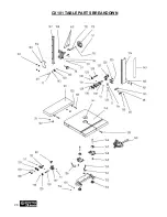
Page 28: ...28 CX101 TABLE PARTS BREAKDOWN ...

Page 29: ...PACKING SLEEVE 129 BEARING 130 EXTERNAL RETAINING RING S10 131 GUIDE SHAFT L 132 SUPPORT 133 CAP SCREW 134 GUIDE POST 135 POINTER 136 137 138 139 TABLE PIN 140 MITER GAUGE ASSY 141 TABLE INSERT 142 TABLE 19MM T SLOT 143 GUIDE POST SCALE 144 POINTER PLATE 145 146 BOLT HEX HD 3 8 2 5L 147 TRUNNION CLAMP SHOE 148 TRUNNION 149 HEX BOLT 5 16 3 4 150 HEX BOLT 3 8 2 151 FLAT WASHER 3 8 152 TRUNNION SUPPO...

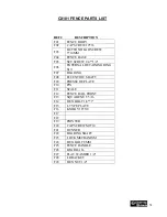
Page 30: ...30 CX101 FENCE PARTS BREAKDOWN ...

Page 31: ... SHAFT F09 PRESSURE PLATE F10 PIN F11 SCALE F12 FENCE RAIL FRONT F13 SQUARE NUT 5 16 F14 HEX BOLT 1 4 1 F15 L TYPE PLATE F16 KNOB 5 16 5 8 F17 F18 F19 POINTER F20 CAP SCREW M6 10 F21 RUNNER F22 BEARING SHAFT F23 LOCK MECHANISM F24 HEX BOLT 8MM F25 FENCE HANDLE F26 REAR RAIL F27 FLAT WASHER 1 4 F28 L BRACKET F29 HEX NUT 1 4 CX101 FENCE PARTS LIST REF DESCRIPTION ...

Page 32: ... returned merchandise will be subject to a minimum charge of 15 for re stocking and handling with the following qualifications Returns must be pre authorized by us in writing We do not accept collect shipments Items returned for warranty purposes must be insured and shipped pre paid to the nearest warehouse Returns must be accompanied with a copy of your original invoice as proof of purchase Retur...

Reviews: