


Maintenance Manual SP 40
Rev. 005
88
Chapter 5
Test & Diagnostic
Messages are codified in order to provide a proper identification of:
-
Test execution
-
Test KO
-
Error code
-
Message to operator
For the detail see tables on next pages.
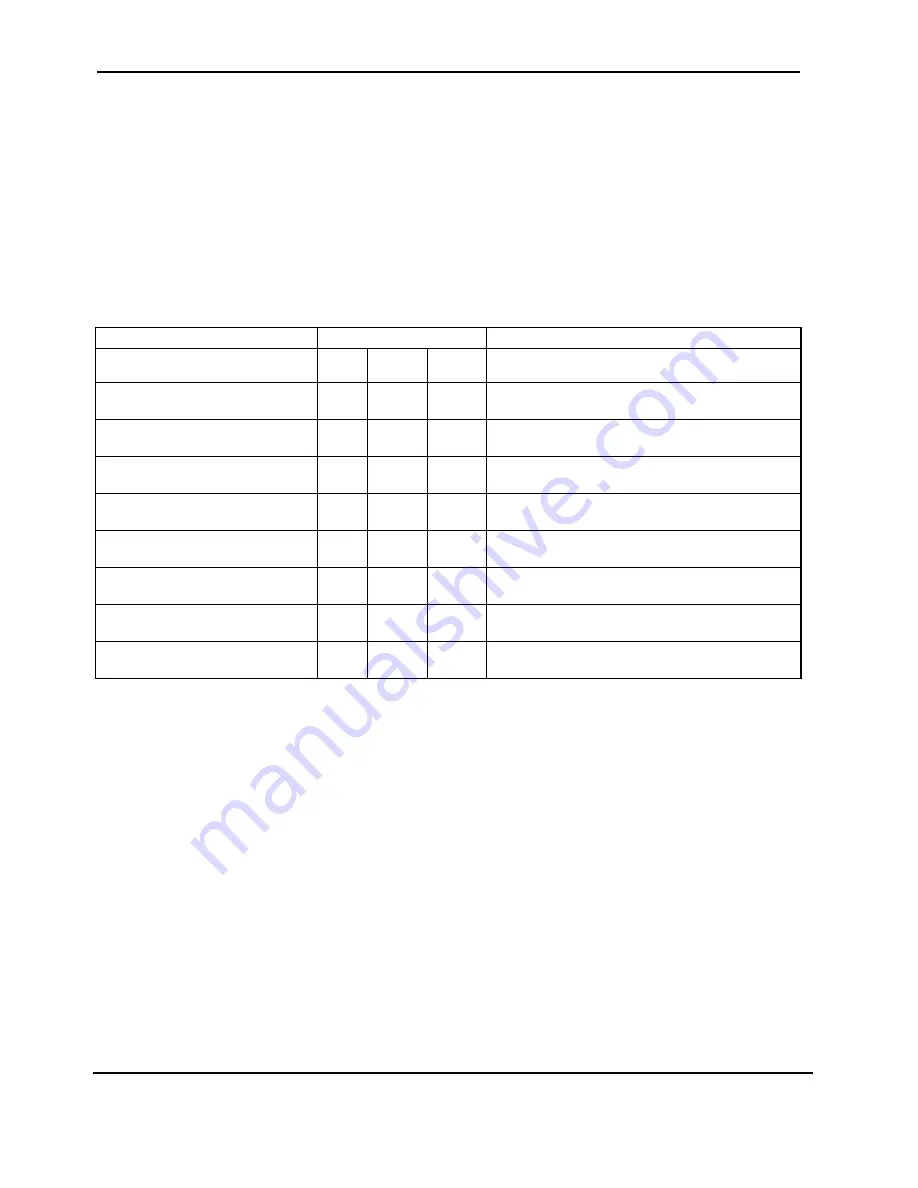
The general rules condition which can appear are reported in the following table.
Type of Operator Message
LEDS
Note
L4
L3
L2
L1
Test number in execution
l
/
¡
The leds are lit following the binary sequence
l
/
¡
l
/
¡
l
/
¡
where L1 is the LSB and L4 is the MSB
Error Code
l
/
¡
/
£
£
l
/
¡
/
£
l
/
¡
O.R.U. Code
£
The leds L1, L2 and L3 are lit or off depending
l
/
¡
l
/
¡
l
/
¡
/
£
by the binary configuration to be showed
Waiting for operator intervention
¥
The L4 is high frequency blinking if an action
£
l
£
of operator is requested (cover open)
Waiting for paper loading
l
The L2 is high frequency blinking if paper
£
¥
£
handling is requested (load or exctract paper)
Waiting for key or paper
¥
The L2 & L4 are high frequency blinking if an
£
¥
£
action on operator panel is requested
Test KO
¡
See chapter 5.7. for the error handling
£
¡
£
End T&D
£
£
£
£
Table 5.1 General rules for T&D operations
During T&D execution in Step by Step, the keys have the following meaning:
STATION 1
Decrement test number
STATION 2
Increment test number
ON LINE
Execute test
After the execution of the selected test a submenu comes activated, so the meaning of the keys becomes:
STATION 1
Repeat test
STATION 2
Skip test (and return to the previous menu)
ON LINE
Loop on the test
Summary of Contents for Compuprint SP 40
Page 1: ...MAINTENANCE MANUAL SP 40...
Page 2: ......
Page 10: ...Maintenance Manual SP 40 Rev 005 i 8 Index Page intentionally left blank...
Page 31: ...Maintenance Manual SP 40 Rev 005 21 Chapter 2 Removals Figure 2 7 Boards Removal...
Page 32: ...Maintenance Manual SP 40 Rev 005 22 Chapter 2 Removals Page intentionally left blank...
Page 35: ...Maintenance Manual SP 40 Rev 005 25 Chapter 2 Removals Figure 2 9 Carriage Motor Assy removal...
Page 41: ...Maintenance Manual SP 40 Rev 005 31 Chapter 2 Removals Figure 2 13 Ribbon Drive Removal...
Page 45: ...Maintenance Manual SP 40 Rev 005 35 Chapter 2 Removals Figure 2 15 Mylar Bar Removal...
Page 47: ...Maintenance Manual SP 40 Rev 005 37 Chapter 2 Removals Figure 2 16 Rear Roller Assy Removal...
Page 51: ...Maintenance Manual SP 40 Rev 005 41 Chapter 2 Removals Figure 2 18 Selector Cam Removal...
Page 57: ...Maintenance Manual SP 40 Rev 005 47 Chapter 2 Removals Figure 2 22 Platen Assy Removal...
Page 128: ...Maintenance Manual SP 40 Rev 005 118 Chapter 6 Paper Specification BLANK PAGE...
Page 143: ......


