Misprints and technical changes reserved
Instruction and Operation Manual
5
3.
Connections and Indications
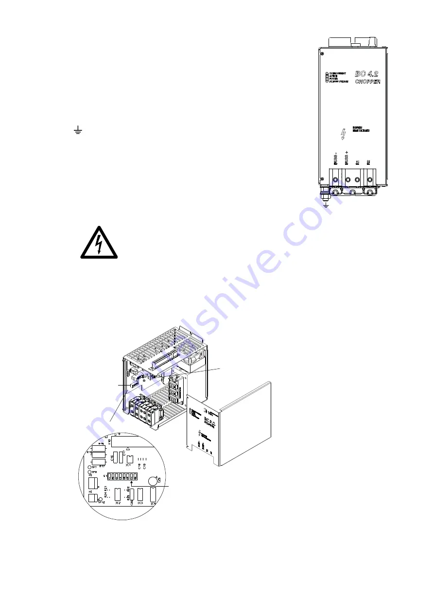
Indications
Overcurrent
red
Overcurrent/Short circuit
Active
clear
Chopper is active
Power
green
Chopper is ready
DC Buss Voltage
red
Buss Voltage
Connections of the terminal blocks
Grounding: Large-area earthing of the cover is
recommended, e.g. mounting on a galvanized
assembly plate.
BUSS-
-connection BUSS-voltage inverter
BUSS+
+connection BUSS-voltage inverter
R1 - R2
a bimetal relay must be connected in series to the
braking resistor. This has to be adjusted to the nominal
current of the brake resistor. (see Chapter 4 Example
of Connection)
Caution !
1.
Do not connect or disconnect the chopper under voltage.
2.
Please take care of the correct polarity.
3.
If you exchange the connections BUSS + and BUSS- the inverter or the
chopper can be destroyed.
4.
Ultrafast semiconductor fuses for the protection of the IGBT is not
installed.
3.1
Design
(Mainboard)
Dipswitch S1.7:
without Master/Slave-Option
ON
at Master/Slave-Option
OFF
Dipswitch S1
ON
OFF
(Optionsboard)


