


1018029-A
Page 11
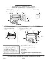
STANDING PILOT
IID PILOT
INSTALLATION
CONTROLS
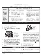
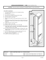
All controls are pre-assembled at the factory. The normal
manifold pressure should be 3.5” w.c. for Natural Gas and 10”
w.c. for Propane Gas. The maximum inlet pressure in the gas
supply pipe should never exceed 7.0” w.c. for Natural Gas or
14” w.c. for Propane Gas. The minimum inlet pressure in the gas
supply pipe should never be lower than 4.5” w.c. for Natural Gas
or 11” w.c. for Propane Gas.
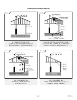
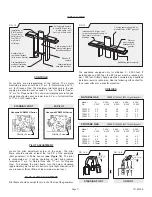
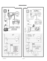
PILOT ADJUSTMENT
Locate the pilot adjustment screw on the valve. The pilot
flame should surround at least the top 3/8” of the powerpile
(pilot generator) or flame sensor
(see Figure 14)
. The pilot
is unregulated so it will be operating at inlet line pressure
(maximum 7” w.c. for Natural Gas and 11” w.c. for Propane
Gas). To decrease the pilot flame, turn the screw clockwise
(approximately six full turns to bottom of pilot light channel) until
you produce sufficient flame at the minimum noise level.
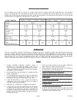
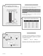
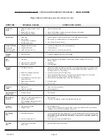
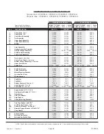
The appliance equipped only for altitudes 0 - 2,000 feet. If
installed above 2,000 feet, the BTU input must be reduced 4%
per 1,000 feet. Orifice change must be completed by a qualified
installer or service technician. See the following orifice chart for
the proper orifice for a specific elevation.
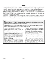
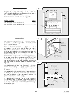
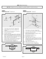
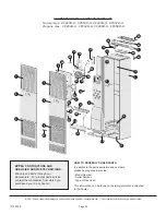
FIG. 12
Installation of
B-W Gas Vent
for one story
buildings or for
first floor of
multi-story
buildings.
Header plate of
vented wall furnace.
(Also acts as firestop)
Use manufacturer’s
method of fastening
pipe to base plate.
Sheet metal screw
base plate to header.
Studs on 16”
centers.
Plate cut away for full
width of stud space
to provide ventilation.
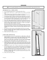
Ceiling plate spacers
to center B-W gas vent
in stud space - nail
securely at both ends.
FIG. 13
Installation of B-W gas vent
for each subsequent ceiling or
floor level of multi-story
buildings.
Firestop spacers supplied by
manufacturer of B-W gas vent.
Plate cut
away to provide
passage of B-W
gas vent.
Nail firestop spacer securely.
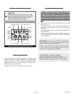
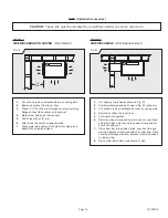
STANDING PILOT
IID PILOT
Honeywell VR8200H Series
Pilot Adj. Screw
Honeywell VR8204H Series
Pilot Adj. Screw
PILOT FLAME ADJUSTMENT
Pilot flame should envelop 3/8 to ½ inch of the tip of the generator.
NATURAL GAS
ORDER KIT #49840 2287-1 High Altitude Kit
Model
0’ -
2,000’ -
4,000’ -
6,000’ -
8,000’ -
No.
2,000’ 4,000’ 6,000’ 8,000’ 10,000’
CF403D 32 34 35 36 40
CF407D 32 34 35 36 40
CF553D 29 30 30 31 32
CF557D 29 30 30 31 32
PROPANE GAS
ORDER KIT #49840 2287-1 High Altitude Kit
Model
0’ -
2,000’ -
4,000’ -
6,000’ -
8,000’ -
No.
2,000’ 4,000’ 6,000’ 8,000’ 10,000’
CF404D 49 50 51 52 52
CF408D 49 50 51 52 52
CF554D 2.15mm 45
47
48
49
CF558D 2.15mm 45
47
48
49
ORIFICES
FIG. 14-B
FIG. 14-A
3/8” to 1/2”
3/8” to 1/2”


