background image


©2005-2008 CoVi Technologies, Inc. All rights reserved. CoVi, the CoVi logo, EVQ-3000, MultiView, and ZUP are trademarks of CoVi Technologies, Inc. CoVi Technologies, Inc. has made every effort to identify trademarked properties and  
owners on this page. All brands and product names used in this document are for identification purposes only and may be trademarks or registered trademarks of their respective companies.


January, 2008 P/N 1DOC 0001022-01 Rev. 4


 8


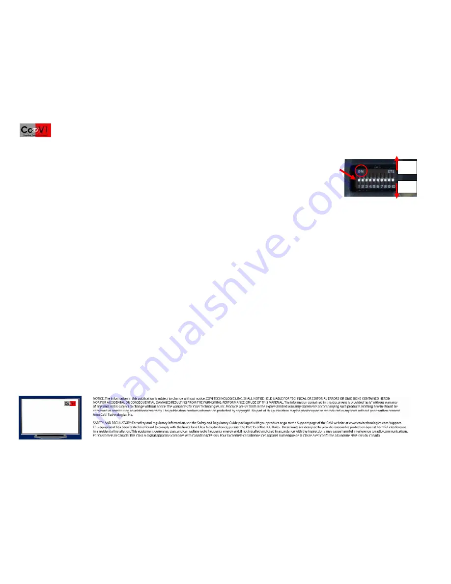
Setting the Camera ID 

Set the camera ID using the dip switches on the camera, shown in the illustration. (See the 

CoVi EVQ-3000 Installer’s

 or

 Product 

guides for dip switch settings.)  


Switches 1-8 (left to right)—Set camera RS-485 address 0-255 (default=1) 


Switch 9—NTSC (OFF/DOWN), PAL (ON/UP) setting (default=DOWN/NTSC) 


Switch 10—Sets the RS-485 connector to either termination mode (OFF/DOWN/LOW) or daisy chain mode (ON/HIGH/UP) 
(default=DOWN/termination mode) 

 
NOTE

: “CTS” is the manufacturer’s name and not a dip switch setting. 

Complete the camera and dome installation 

1.  After setting up the camera yoke assembly, reinstall the dome bubble on the dome cover assembly with the screws provided (use the tamper-proof screws and hex tool 

provided for the vandal-resistant dome). 

2.  Adjust the included inner liner to conceal the camera position. 

After camera installation 

See the 

CoVi EVQ-3000 Product Guide 

for


configuration options using CoVi RCCU software. 


CoVi Technologies, Inc. 

 6300 Bridgepoint Parkway 

Suite 300, Building II 

Austin, Texas 78730 

888-987-2684 (toll free, Support) 

512-527-5900 (local and 

international) 

ON 

OFF 

Summary of Contents for EVQ-3000

Page 1: ...1 Base mounting screws 2 4 Top conduit opening 7 Mounting paddles 2 2 Anchor clips 5 Camera yoke assembly 8 Dome bubble 3 Base housing center a and lip b 6 Yoke mounting screws 4 9 Breakout board mou...

Page 2: ...akout board 1 Read the GENERAL INSTALLATION REQUIREMENTS to ensure they are met 2 Read the WARNINGS and CAUTIONS 3 Remove the dome assembly 9 from the base housing 6 by twisting the dome counter clock...

Page 3: ...connectors IMPORTANT We recommend that you install a 4 double gang box with a mud ring or weatherproof Bell box to protect the breakout board 1 Read the section GENERAL INSTALLATION REQUIREMENTS to e...

Page 4: ...and Ethernet cables between the EVQ 3000 and the Breakout Board and to the video outputs 1 Connect 24V AC or 12V DC to the breakout board power terminals 1 the breakout board power LED should be ON 2...

Page 5: ...on this page All brands and product names used in this document are for identification purposes only and may be trademarks or registered trademarks of their respective companies January 2008 P N 1DOC...

Page 6: ...f their respective companies January 2008 P N 1DOC 0001022 01 Rev 4 6 Video setup and focusing RS 485 connection to a PC Use the diagram below to connect the Dome Camera to a PC through an RS232 to RS...

Page 7: ...All brands and product names used in this document are for identification purposes only and may be trademarks or registered trademarks of their respective companies January 2008 P N 1DOC 0001022 01 Re...

Page 8: ...address 0 255 default 1 Switch 9 NTSC OFF DOWN PAL ON UP setting default DOWN NTSC Switch 10 Sets the RS 485 connector to either termination mode OFF DOWN LOW or daisy chain mode ON HIGH UP default D...

Reviews: