


Quick Install Guide for the CoVi EVQ-3000 Mini-Dome Camera
3
©2005-2008 CoVi Technologies, Inc. All rights reserved. CoVi, the CoVi logo, EVQ-3000, MultiView, and ZUP are trademarks of CoVi Technologies, Inc. CoVi Technologies, Inc. has made every effort to identify trademarked properties and
owners on this page. All brands and product names used in this document are for identification purposes only and may be trademarks or registered trademarks of their respective companies.
January, 2008 P/N 1DOC 0001022-01 Rev. 4
Installing the Vandal Resistant Mini-Dome
(hard ceilings or walls)
IMPORTANT
: This section describes installing the EVQ-3000 Vandal Resistant Mini-Dome. See the
CoVi EVQ-3000 Product Guide
for information about using the CoVi Remote Camera Control Utility (RCCU) software.
PACKAGE CONTENTS (ALL PRODUCTS):
•
BOX 1: Base housing, dome bubble, and fasteners
•
BOX 2: Camera yoke assembly
•
CABLING: 7-foot plug-and-play Cat. 5 flat cable with breakout board (dual video, power, RS-485) and
mounting screws
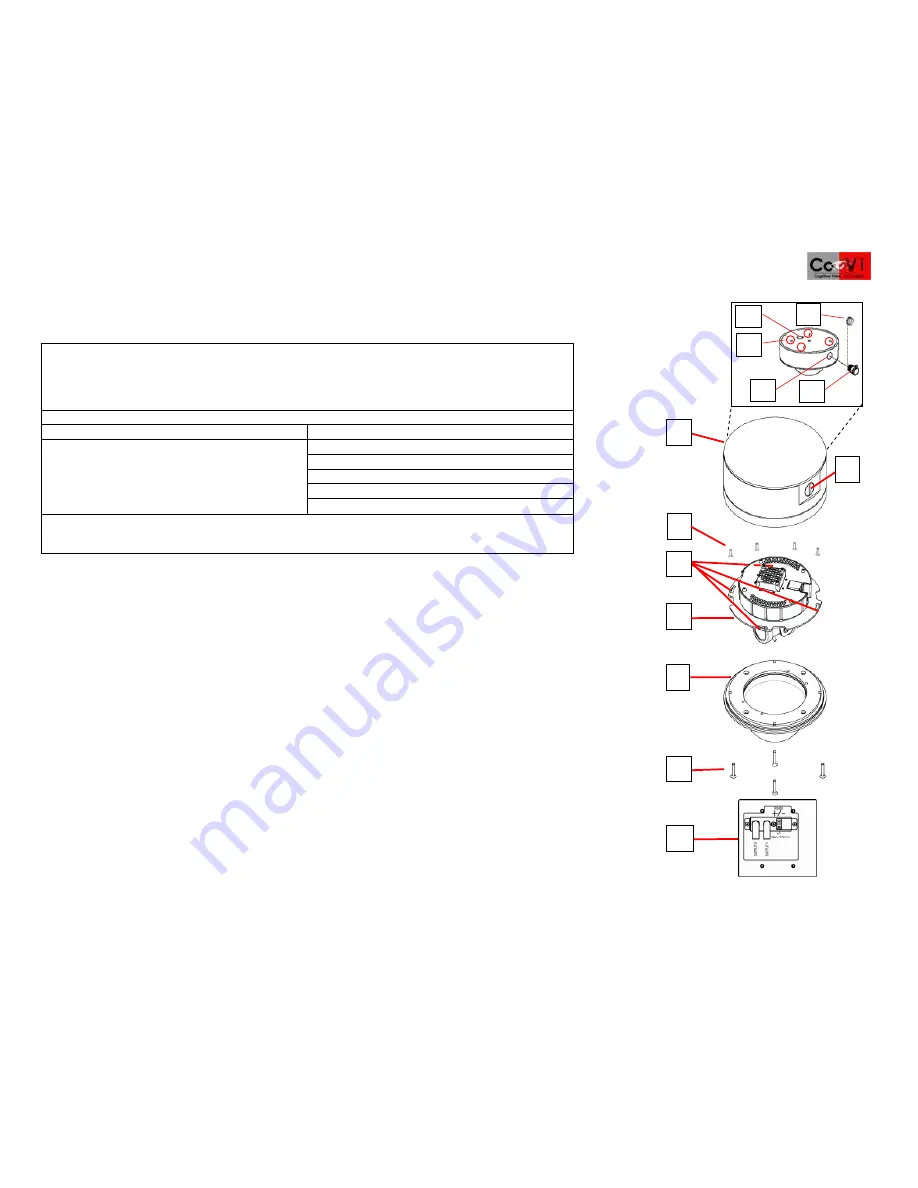
VANDAL RESISTANT MINI-DOME COMPONENTS:
[1] Base housing
[2] Side entry (vandal resistant)
[3] Yoke mounting screws (4)
[4] Camera locking slots (4)
[5] Camera yoke assembly
[6] Dome bubble
Exploded base housing assembly:
[A] Metal entry plug
[B] Top conduit opening
[C] Mounting holes (4)
[D] ½-inch conduit connector
[E] Side conduit opening
[7] Tamper-proof base mounting screws (4)
[8] Breakout board (mounted to junction box cover): contains RJ-45, RS-485, two BNC video, power connectors.
IMPORTANT
: We recommend that you install a 4” double gang box with a mud ring or weatherproof “Bell” box
to protect the breakout board.
1. Read the section “GENERAL INSTALLATION REQUIREMENTS” to ensure they are met.
2. Read the WARNINGS and CAUTIONS.
3. Carefully remove the dome bubble [
6
] from the base housing [
1
].
NOTE
: The bubble is not attached to the base with mounting
straps. Keep the protective plastic on the dome bubble to ensure the it is not scratched or damaged until ready to use.
4. Remove the camera yoke assembly [
5
] from its box and keep in a safe place until ready to install. See the section “Installing
the Camera Yoke Assembly” in this
Quick Install Guide
.
5. Pull flat Cat. 5 cable through the top [
B
] or side conduit opening [
E
]. (Because of the elastomer liner on the base housing, the
top conduit opening [
B
] as well as the mounting holes [
1B
] can only be seen from inside the dome.)
6. Find the desired mounting location, using the four mounting holes [
C
] inside the base housing as a drilling template (see Inset).
7. Mount the base housing to the mounting surface using the screws and fasteners provided. OPTIONAL: Mount this to a junction
box (not provided).
8. (OPTIONAL if using the side conduit opening [
E
]) Remove the metal entry plug [
A
] from the side conduit opening [
2
] and install
the ½-inch conduit connector [
D
].
9. Install the four camera mounting screws [
3
] in the base housing [
1
]. Do not tighten them. They lock into camera locking slots [
4
].
(See Step 10.)
10. You are now ready to install and configure the camera yoke assembly [
5
]. See the sections "Installing the breakout board" and
"Installing the camera yoke assembly."
6
2
7
8
3
5
4
A
1
D
B
C
E


