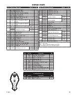
Country Heart 2000 L Owner'S Operation And Instruction Manual Download Page 21

Ussc 21

REPAIR PARTS

Key

Part No.

Description

Qty.

1

25491

Feed Door, Painted (40484)

1

2

25692

Handle, Painted (40515)

1

3

83506

3/8 x 1-1/4 Roll Pin

1

4

891135

Spring Handle - LG

1

5

88066

Rope Gasket - 5/8”

4.6 Ft

6

88087

Glass Gasket - 1/8 thk x 1” wide

3.7 Ft

7

891131

Ceramic Glass

1

8

25464

Top Glass Retainer

1

9

25465

Bottom Glass Retainer

1

10

83202

10-24 x 3/8 Pan Head Phillips Screw

4

11

83278

Washer - 7/32 ID x 1/2 OD

4

1

69515MB

Feed Door Assy.

1

2

25080B

Feed Door Latch

1

3

83508

5/16-18 x 3/4 Hex Head Bolt

1

4

83338

5/16-18 Lock Nut

1

5

891373

Door Hinge Pad

2

6

83045A

Washer, 3/8” ID x 7/8” OD

2

7

83274

3/8-16 Lock Nut

2

8

86643

Tube, Secondary Air (Ø0.16 

holes)

2000

1

2500

2

9

86645

Tube, Secondary Air (Ø0.22 

holes)

2000

2

2500

2

10

891515

Retainer, Tube (1 per Secondary Tube)

3 - 5

11

88146

Refractory Insulation

2000

1

88138

2500

1

12

891516

Damper Slide

1

13

891517

Hearth Plate

1

14

891331

Spring Handle - Small

1

15

891514

Shield, Rear

1

16

891528

Air Deflector

1

17

40292A

Flue Collar

1

18

88032

Flue Collar Gasket

1.7 Ft

19

83432

5/16-18 x 1-1/2 Hex Head Bolt

3

20

83045

Washer, 5/16” ID x 3/4” OD

3

21

83431

Weld Tab

3

22

89066

Firebrick 

(4.5 x 9 x 1.25)

2000

16

2500

18

23

891414

Firebrick (2-1/4 x 9)

2

24

24103

Firebrick (4-1/2 x 4-1/2)

1

25

891530

Firebrick (4-1/2 x 7-1/2 )

1

26

40561

Ash Plug

1

27

891777

Pedestal Wrapper

2000

1

891788

2500

1

28

891778

Pedestal Bottom

2000

1

891521

2500,

1

29

891523

Pedestal Back

1

30

891527

Ash Pan

1

31

891137

Handle

1

32

40496

Corner Trim

2

33

83466

8-32 x 1/4 Self Tapping Screw

8

34

891524

Front Pedestal Trim

1

35

891779

Right Side Pedestal Trim

2000

1

891526

2500

1

36

891780

Left Side Pedestal Trim

2000

1

891525

2500

1

N/S

u

891944

Trim, One Piece

2000

1

891945

Trim, One Piece

2500

1

37

69354

B36 Blower Assembly

1

N/S  =  Not Shown


=  Used on heaters manufactured in 2011

All components common except where noted.

Key

Part No. Description

Model

Qty.

Key

Part No. Description

Model

Qty.

Key

Part No. Description

Model

Qty.

Key

Part No. Description

Model

Qty.

For Models with Legs

Key

Part No.

Description

Qty.

Z

40566

Leg, Cast Iron

2

N/S

83339

Bolt, 1/4-20 x 3/4

8

Summary of Contents for 2000 L

Page 1: ... bodily injury or even death Improper Installation Could Void Your Warranty SAFETY TESTED TO UL 1482 and ULC S627 US ENVIRONMENTAL PROTECTION AGENCY PHASE II CERTIFIED WOODSTOVE WASHINGTON STATE APPROVED MOBILE HOME APPROVED U S ONLY United States Stove Company 227 Industrial Park Road P O Box 151 South Pittsburg TN 37380 SAVE THESE INSTRUCTIONS THIS MANUAL WILL HELP YOU TO OBTAIN EFFICIENT DEPEND...

Page 2: ... LEAVE THE STOVE UNATTENDED WHEN THE DOOR IS SLIGHTLY OPENED DO NOT BURN GARBAGE FLAMMABLE FLUID SUCH AS GASOLINE NAPHTHA OR MOTOR OIL DO NOT CONNECT TO ANY AIR DISTRIBUTION DUCT OR SYSTEM ALWAYS CLOSE THE DOOR AFTER THE IGNITION Combustible Model Wood Colors Metallic Black Flue Pipe Diameter 6 152 5mm Flue Pipe Type Standard Single Wall or Double Wall Black or Blued Steel 2100 F 650 C Minimum Chi...

Page 3: ...______ Reason for Purchase qAlternative Heat qMain Heat Source qDecoration qCost qOther_________________________ What was the determining factor for purchasing your new appliance _______ I have read the owner s manual that accompanies this unit and fully understand the Installation q Operation q and Maintenance q of my new appliance Print Name Signature Date Please attach a copy of your purchase r...

Page 4: ...4 Ussc CUT HERE CUT HERE Ê É Fold Here Fold Here United States Stove Company P O Box 151 South Pittsburg TN 37380 Fold Here Place Stamp Here ...

Page 5: ...required for your particular chimney installation For mobile homes see page 13 Assembly Flue Collar Assembly 1 Mount the flue collar to the top of the unit as shown using the 3 5 16 18 x 1 1 2 bolts 3 washers and 3 weld tabs provided in the parts box Room Air Deflector Assembly 1 Locate the Room Air Deflector Using the three 3 1 2 Tek Screws provided mount the deflector to the unit as shown in the...

Page 6: ...HE SUPPLY CORD NEAR OR ACROSS HOT SURFACES Step 1 Fix the assembly to the back of the stove with the four screws provided Pedestal Trim Assembly Assemble trim pieces as shown with the screws provided in the parts bag Washers may not be necessary After trim assembly attach to the pedestal base at the location shown using the screws provided Ash Pan Assembly Remove ash pan from firebox Under the fir...

Page 7: ...SH AIR INTO THE ROOM OR SPACE HEATED SHALL BE PROVIDED WHEN REQUIRED POSITIONING THE STOVE It is very important to position the wood stove as close as possible to the chimney and in an area that will favor the most efficient heat distribution possible throughout the house The stove must therefore be installed in the room where the most time is spent and in the most spacious room possible Recall th...

Page 8: ...value k factor is given with a required thickness T in inches R 1 k x T C factor is given R 1 C Example If the floor protector is 4 brick with a C factor of 1 25 over 1 8 mineral board with a k factor of 0 29 the total R value of the system is 4 brick C 1 25 R 1 1 25 0 8 1 8 mineral board K 0 29 R 1 0 29 x 0 125 0 431 Total R Rbrick Rmineral 0 8 0 431 1 231 Total R is greater than 1 2 the system i...

Page 9: ... must not pass through an attic or roof space closet or similar concealed space a floor or a ceiling For Canadian installations where passage through a wall or partition of combustible construction is desired the installation must conform to CAN CSA B365 A flue pipe crossing a combustible wall must have a minimum clearance of 18 457 2mm To reduce flue clearances from combustible materials contact ...

Page 10: ...end of the section toward the chimney Any installation with a horizontal run of chimney pipe must conform to NFPA 211 You may contact NFPA National Fire Protection Association and request the latest edition of the NFPA Standard 211 To insure a good draft the total length of the coupling pipe should never exceed 8 to 10 2 4m to 3 04 m Except for cases of vertical installation cathedral roof style w...

Page 11: ...s the draft effect your stove s performance is directly dependent on an adequate draft from your chimney The following recommendations may be useful for the installation of your chimney 1 Do not connect this unit to a chimney flue serving another appliance 2 It must rise above the roof at least 3 0 9m from the uppermost point of contact 3 The chimney must exceed any part of the building or other o...

Page 12: ...e same manufacturer and install the ceiling support package or wall pass through and T section package firestops where needed insulation shield roof flashing chimney cap etc Maintain proper clearance to the structure as recommended by the manufacturer The chimney must be the required height above the roof or other obstructions for safety and proper draft operation ...

Page 13: ...As sociation NFPA by having it inspected by a professional Make sure there are no cracks loose mortar or other signs of deterioration and blockage Have the chimney cleaned before the stove is installed and operated When connecting the stove through a combustible wall to a masonry chim ney special methods are needed ...

Page 14: ...l chimney connector and a minimum 24 gage ventilated wall thimble which has two air channels of 1 25 4 mm each construct a wall pass through There shall be a minimum 6 152 4 mm sep aration area containing fiberglass insulation from the outer surface of the wall thimble to wall combustibles Support the wall thimble and cover its opening with a 24 gage minimum sheet metal sup port Maintain the 6 152...

Page 15: ...t there is combustion present 3 Opening a window slightly on a calm windless day alleviates any of the above symptoms 4 The house is equipped with a well sealed vapor barrier and tight fitting windows and or has any powered devices that exhaust house air 5 There is excessive condensation on windows in the winter 6 A ventilation system is installed in the house For use in MOBILE HOMES U S installat...

Page 16: ... conditions it may rot instead of drying This point cannot be over stressed the vast majority of the problems related to the operation of a wood stove is caused by the fact that the wood used was too damp or had dried in poor conditions These problems can be ignition problems creosote build up causing chimney fires low energy yield blackened windows incomplete log combustion Smaller pieces of wood...

Page 17: ...end the following burn procedures HEATING Controlled combustion is the most efficient technique for wood heating because it enables you to select the type of combustion you want for each given situation The wood will burn slowly if the wood stove air intake control is adjusted to reduce the oxygen supply in the combustion chamber to a minimum On the other hand wood will burn quickly if the air con...

Page 18: ...ense in the relatively cool chimney flue of a slow burning fire As a result creosote residue accumulates on the flue lining When ignited this creosote makes an extremely hot fire The chimney connector and chimney should be inspected at least once every two months during the heating season to determine if a creosote build up has occurred If creosote has accumulated 3mm or more it should be removed ...

Page 19: ...triking or slamming shut Do not use the stove if the glass is broken If the glass on your stove breaks replace only with the glass supplied from your heater dealer Never substitute other materials for the glass To replace the glass remove the screws retaining the glass mouldings inside the door Remove the mouldings and replace the damaged piece with a new one Perform the procedure backwards after ...

Page 20: ...20 Ussc REPAIR PARTS 5 6 7 4 3 2 17 18 19 20 21 13 12 27 28 30 29 16 15 37 1 22 24 25 26 35 32 33 34 36 31 14 23 9 8 10 11 4 3 1 5 6 7 2 9 8 10 11 Feed Door Assembly ...

Page 21: ...528 Air Deflector 1 17 40292A Flue Collar 1 18 88032 Flue Collar Gasket 1 7 Ft 19 83432 5 16 18 x 1 1 2 Hex Head Bolt 3 20 83045 Washer 5 16 ID x 3 4 OD 3 21 83431 Weld Tab 3 22 89066 Firebrick 4 5 x 9 x 1 25 2000 16 2500 18 23 891414 Firebrick 2 1 4 x 9 2 24 24103 Firebrick 4 1 2 x 4 1 2 1 25 891530 Firebrick 4 1 2 x 7 1 2 1 26 40561 Ash Plug 1 27 891777 Pedestal Wrapper 2000 1 891788 2500 1 28 8...

Page 22: ...22 Ussc NOTES ...

Page 23: ...Ussc 23 NOTES ...

Page 24: ...model number which is on the nameplate attached to the heater when ordering repair parts always give the following infor mation as shown in this list 1 The part number 2 the part description 3 the model number ________________________ 4 the serial number ________________________ how to order repair parts united states stove company 227 industrial park road p o box 151 south pittsburg tn 37380 423 ...

Reviews: