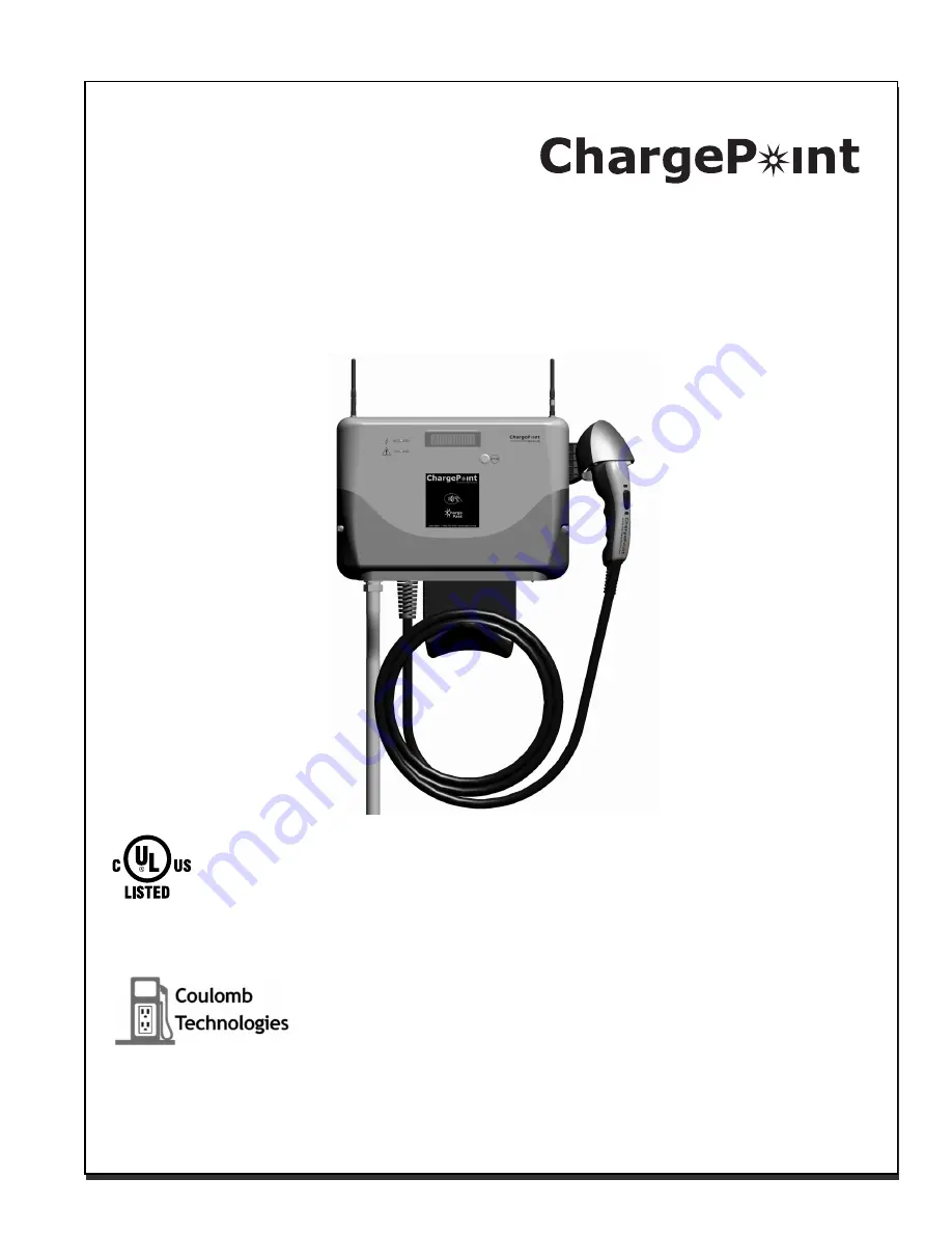
Coulomb Technologies ChargePoint CT500 Installation Manual Download Page 1

CT500 
ChargePoint

®

 Networked Charging Station

Installation

Guide

Part Number: 75-001024-01  Revision: 1.0

Coulomb Technologies Inc.
1692 Dell Ave.
Campbell, CA 95008-6901 USA
US toll free: +1-877-370-3802
www.coulombtech.com
www.mychargepoint.net

by Coulomb Technologies

®


Summary of Contents for ChargePoint CT500

Page 1: ...rging Station Installation Guide Part Number 75 001024 01 Revision 1 0 Coulomb Technologies Inc 1692 Dell Ave Campbell CA 95008 6901 USA US toll free 1 877 370 3802 www coulombtech com www mychargepoi...

Page 2: ...d other information in this manual are subject to change at any time without prior notice Warranty information and disclaimer Your use of or modification to the ChargePoint Charging Station in a manne...

Page 3: ...g cable is positioned so it will not be stepped on tripped over or subjected to damage or stress SAVE THESE INSTRUCTIONS Cleaning the CT500 Do not use cleaning solvents to clean any of the CT500 s com...

Page 4: ......

Page 5: ...or correct contents 2 2 Step 2 Attach holster 2 3 Step 3 Remove front panel 2 4 Step 4 Mount to wall 2 5 Step 5 Install conduit 2 7 Step 6 Connect wires to wiring terminals 2 8 Step 7 Replace front pa...

Page 6: ......

Page 7: ...s page 1 3 Ensure that the type of modem in the CT500 station that you are installing is compatible with the type of modem coverage available at the installation site CDMA or GPRS Disconnect power Det...

Page 8: ...terminated per SAE J1772TM specification Power Measurement 2 15 minute intervals Local Area Network 2 4 GHz 802 15 4 dynamic mesh network Wide Area Network Commercial CDMA or GPRS cellular data netwo...

Page 9: ...BUS 40 A GND L1 L2 240 V METER NEU L2 L1 GND MAIN BREAKER NEU BUS GND BUS 40 A GND L1 L2 240 V METER 208 V 3 240 V 1 LOCAL SERVICE PANEL LOCAL SERVICE PANEL 40A 2 POLE BREAKER MAY BE CONNECTED TO ANY...

Page 10: ......

Page 11: ...lange lag bolts 4 Overview of steps Installing the CT500 ChargePoint Charging Station involves a few simple steps 1 Check box for correct contents see page 2 2 2 Attach holster see page 2 3 3 Remove f...

Page 12: ...T500 ships with either one or two antennas depending on the specific model that was ordered IN IN IN IN X IN DIA 4 ENCLOSURE ENVELOPE 4 7ALL OUNTING OLE 0ATTERN 4 0 CT500 ChargePoint Networked Chargin...

Page 13: ...Installation Instructions 2 3 Step 2 Attach holster Using a 2 Phillips screwdriver attach the holster to the main assembly using the three supplied Holster bolts...

Page 14: ...ChargePoint Charging Stations 2 4 Step 3 Remove front panel Using a 2 Phillips screwdriver loosen the 2 captive screws located on each side of the front panel Pull the front panel downward to remove...

Page 15: ...es in the wall as illustrated Use the supplied template to ensure correct alignment IMPORTANT The top of the CT500 must be mounted no higher than a maximum height of 48 above the surface to comply wit...

Page 16: ...ChargePoint Charging Stations 2 6 Step 4 Cont d Align the CT500 to the mounting surface and fasten to the wall using a 3 8 socket wrench to fasten the four x 2 lag bolts fasten it to the wall...

Page 17: ...TE The CT500 has four conduit openings three of which are covered If you remove a cover use it to cover the remaining unused conduit opening After running the wiring through 19 mm conduit insert the c...

Page 18: ...Requires dedicated 40A breaker Use copper conductors only Do NOT provide GFCI protection at panel The CT500 has built in GFCI protection In areas with frequent thunder storms add surge protection at t...

Page 19: ...front panel Align the front panel with the main assembly and push upwards into place until the edges meet Using a 2 Phillips screwdriver tighten the two captive screws located on each side of the fron...

Page 20: ...wo antennas depending on the specific model that was ordered Follow these rules when installing the antenna s Always install the antenna WITH the yellow band on the right side Always install the anten...

Page 21: ...r to Chapter 3 Troubleshooting for a description of error messages Ensure that neither light on the left side of the station s display is illuminated or blinking RED This indicates that the station ha...

Page 22: ......

Page 23: ...500 s display illuminates or blinks RED read the display for information about the type of error that has occurred Power up errors The follow messages can occur when the station powers up FAULT GFCI T...

Page 24: ...station detected a ground fault see message above and made three unsuccessful attempts to continue charging Or the station detected a ground fault when attempting to begin a charging session Solution...

Page 25: ...sage continues to be displayed press and hold the STOP button for 10 seconds to reboot the CT500 If the message is still displayed call Coulomb Customer Support at 1 888 758 4389 FAULT RELAY STUCK CLO...

Page 26: ......

Page 27: ......

Page 28: ...Coulomb Technologies Inc 1692 Dell Ave Campbell CA 95008 6901 USA US toll free 1 877 370 3802 www coulombtech com www mychargepoint net...

Reviews: