One-Channel Video Receiver
3
Chapter 2 — Installation
2.1 Package Contents
Network Video Receiver
DC Adapter (5V)
Power Cord
Installation CD (INIT)
User’s Manual (Receiver, INIT)
Wall-mount Kits
Audio Y-Connector
USB Mouse
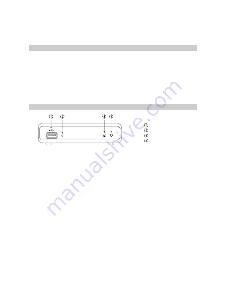
2.2 Front Panel
USB Port
Factory Reset Switch
Network LED
Power LED
USB Port:
Connect a USB mouse to control video monitoring on a connected monitor or a USB flash
drive to upgrade the software. Disconnect power from the receiver and connect a USB flash drive
containing the upgrade package file (.rui and autorun.txt) to the receiver. Connect power to the receiver,
and the software will be upgraded automatically. You can upgrade the software remotely by running
the INIT program. Refer to the INIT User’s Manual for details on remote software upgrade.
Factory Reset Switch:
Use to return all settings to the original factory settings. See below for details.
Network LED:
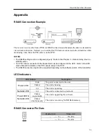
Displays network connection status. Refer to
Appendix A – LED Indicators
for details.
Power LED:
Displays system operating status. Refer to
Appendix A – LED Indicators
for details.
Factory Reset
This switch will only be used on the rare occasions that you want to return all the settings to the original
factory settings.
CAUTION: When performing a Factory Reset, you will lose any settings you have saved.
Disconnect the power adapter from the receiver
→
Poke a straightened paperclip into the factory reset
switch hole
→
Connect the power while holding the reset switch.
→
Release the switch when the
Network and Power LEDs blink together
→
The receiver resets to factory defaults and restarts after
completing the factory reset.
You can perform a factory reset while the receiver is turned on by poking a straightened paperclip
into the factory reset switch hole and releasing the reset switch. A factory reset also can be performed
remotely by running the INIT program. The receiver restarts after completing the factory reset. Refer
to the INIT User’s Manual
for details on remote factory resetting.
Summary of Contents for CR1000INR
Page 1: ......
Page 2: ......
Page 6: ...User s Manual iv ...


