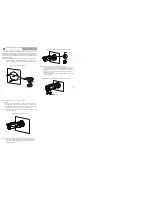
Step 4 Loosen the fixing screw (or locking ring )to adjust the
position and image so that the camera faces the monitored
area, then tighten the fixing screw (the locking ring), as
shown in figure 3-3.
F
igure
3
-
3
Adjusting the monitoring direction
Locking ring
Fixing screw
Tighten
Loosen
you can route cables from the top or from aside. If you use the top
routing method, drill a hole in the surface first. If you use the aside
routing method. When you route cables from aside, Please route
the cable out from the side gap at the bottom of the camera.
NOTE
Step
3
Install the camera on the ceiling or wall, and fix the screws
as shown in figure 3-2.
Figure 3-2
Installing camera
Step 5 (This step is applied for MF products only).
For Figure 3-4,unscrew the fixing screw and open the lens
cover, Use the focusing lever to adjust the lens and check
images on the analog monitor until the captured images
are clear. Then, lock the focusing lever, screw the cover
and fasten the screw.
For Figure 3-5, adjust view angle and focal length by using
an adjusting tool.
Figure 3-4
Adjusting the view angle and focal length
Installation Steps:
Step 1
Stick the Installation location sticker on the ceiling or wall,
Drill three holes based on the marks on the sticker. Drive
the swell plastic buttons into the holes, as shown in figure
3-1.
The Bullet HDVI Camera can be installed on the ceiling or wall. If
the camera is installed on a concrete wall, install the swell plastic
button before installing the bracket. If the camera is installed on a
wooden wall, use self-tapping screws to install the bracket directly.
3 Device Installation
Figure 3-1
Installing camera
Step
2
Connect the Power and video cable.
Focusing cover


