background image

− 12 −

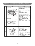
Operating Procedure

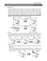
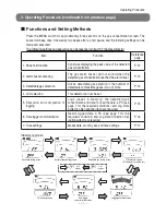
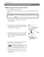
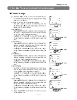
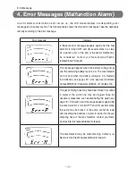
 Peak Hold Settings

With the peak hold function set, the peak value of gas concentration detected will be displayed 
continuously.

(1)  Press the MENU switch for approximately three seconds 

while the gas concentration screen is displayed to display 
the peak hold setting screen (see page 11).

(2)  Press the MENU switch to start the peak hold settings.

The 1 PE indication will change from flashing to steady 
illumination, and OFF will change from steady illumination 
to flashing.

(3)  Press the LIGHT switch (

) to change from OFF to ON.

(4)  Press the MENU switch to enter the settings. The ON 

indication will change from flashing to steady illumination, 
and 1PE will change from steady illumination to flashing.

(5)    Press  the  POWER  switch  and  return  to  the  gas 

concentration screen. Make sure that PEAK is flashing. 
To cancel the peak-hold function, take steps similar to the 
above to turn OFF the function.

3. Operating Procedure (continued from previous page)

Note

The  peak  hold  function  can  be 
canceled by turning the Gas Detector 
OFF, then ON again.

Flashes

Press

SYMBOL.

Flashes

Flashes

Flashes

Flashes

Press

SYMBOL.

Press

SYMBOL.

Press

SYMBOL.

Summary of Contents for XP-3110

Page 1: ...listed on the left Please keep this instruction manual available for quick reference when needed Before use carefully read this instruction manual and fully understand the content XP 3110 Combustible...

Page 2: ...arm Buzzer Silence Settings 13 Changing the Sample Gas 14 Logging 15 Data Logger Communications Screen 16 Time Settings 17 4 Error Message Malfunction Alarm 18 5 Replacement of Consumable Parts 19 Fil...

Page 3: ...eration has not been confirmed in other OS versions Hard disk Free space of 6 Mbytes or more CD ROM drive A CD ROM drive capable of reading CD R data The software is provided in a CD R disc USB port A...

Page 4: ...g the Gas Detector to wear antistatic clothing and electrically conductive shoes antistatic work shoes The floor should also be electrically conductive with an electrical leakage resistance of 10 M or...

Page 5: ...has an explosion proof construction Do not disassemble or modify the Gas Detector or change the structure or electric circuits of the Gas Detector Otherwise the explosion proof performance of the Gas...

Page 6: ...ampling pipe connection port Connects to the gas sampling hose 3 Exhaust port Exhausts sampled gas 4 Buzzer opening Sounds a buzzer 5 Gas type seal Displays the model number and the types of detectabl...

Page 7: ...range of the bar graph 10 LCD sub screen Displays gas concentration and messages J Indicates time K Displays a gas number confi rmed if the number of detectable combustible gases is two or more 11 Co...

Page 8: ...k pocket Used to hold the sampling hose or provided filter No Name Function 1 Gas sampling hose Leads gas to the Gas Detector 1 m long 2 Coupler Connects to the Gas Detector 3 Drain filter DF 4 Preven...

Page 9: ...ntration screen will be displayed WARNING Be sure to place the connected gas sampling hose in clean air when turning ON the Gas Detector Zero calibration is done automatically The wrong gas concentrat...

Page 10: ...ressing the BZ STOP switch The screen will return to the clock display in approximately three seconds To change the sample gas refer to page 14 The gas number however cannot be confirmed during a gas...

Page 11: ...sure to conduct zero adjustment or the precise measurement of gas may not be possible Range To change the bar graph range press the POWER switch while the gas concentration screen is displayed The ra...

Page 12: ...oncentration reaches the alarm level again the gas alarm buzzer will sound again If the pointer scales out when detecting high concentration gas OL will be displayed High concentration gas may have an...

Page 13: ...able gas selection Allows detectable gas selection if the number of detectable combustible gases is two or more P 14 4 LCD selection This detector can not be set 5 Execution and completion of logging...

Page 14: ...lumination to flashing 3 Press the LIGHT switch to change from OFF to ON 4 Press the MENU switch to enter the settings The ON indication will change from flashing to steady illumination and 1PE will c...

Page 15: ...dy illumination to flashing 3 Press the BZ STOP switch and change ON to OFF will change to 4 Press the MENU switch to enter the settings The OFF indication will then change from flashing to steady ill...

Page 16: ...ing and 1 01 will start flashing 3 Press the LIGHT switch to select the gas number 4 Press the MENU switch to enter the settings The 1 02 indication will then change from flashing to steady illuminati...

Page 17: ...d OFF will change from steady illumination to flashing 3 Press the LIGHT switch to change OFF to ON 4 Press the MENU switch to enter the settings The ON indication will then change from flashing to st...

Page 18: ...op flashing and ON will start flashing Data logger communication with the PC will then be possible Operate the PC for data logger communication 4 When communication is finished press the POWER switch...

Page 19: ...the setting and press the MENU switch to enter the value 5 Date Setting When the MENU switch is pressed CL3 will change from flashing to steady illumination and the date value will change from steady...

Page 20: ...the battery voltage drops and the remaining battery level is low The Gas Detector will not work when the battery voltage is low Replace the batteries see pages 20 Use approved batteries Duracell MN150...

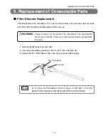
Page 21: ...2 Use a small flat blade screwdriver to remove the O ring in the filter case 3 Replace the FE 2 Filter Element with a new one and reassemble the parts WARNING If water is drawn into the inside of the...

Page 22: ...into the case part No 3620584053 and zip it shut before entering the hazardous location WARNING Use Panasonic LR6XJK Toshiba LR6 or Duracell MN1500 batteries Use of any other manufacturer or type wil...

Page 23: ...in filter clean the inside of the drain filter and 1 m long gas sampling hose and replace the filter element with a new one see page 19 Remaining battery level If the remaining battery level is low re...

Page 24: ...rned on even if you press the POWER switch T h e p o l a r i t y i s incorrect Install batteries again in the correct polarity Battery r e p l a c e m e n t P20 Battery life Replace the batteries The...

Page 25: ...mos s sole option replacement or repair of such non conforming product or refund of the original purchase price of the non conforming product In no event will New Cosmos be liable for any other specia...

Page 26: ...lkaline batteries Approx 30 hrs Alkaline batteries Approx 20 hrs Approx 15 hrs Methane specifications At an ambient temperature of 20 C with the alarm backlight and data logging function turned OFF Op...

Page 27: ...Rev 2009 12 08 UL 60079 11 5th Ed Rev 2011 05 05 UL 60079 1 6th Ed Rev 2009 04 10 EN 60079 0 2012 EN 60079 0 2012 EN 60079 11 2012 EN 60079 1 2007 IEC 60079 0 6th Ed Corr 1 IEC 60079 0 6th Ed Corr 1...

Page 28: ...d the resistance of the platinum filament will decrease This resistance change is output as a voltage deviation change of the bridge circuit The sensor is very sensitive to low concentrations making i...

Page 29: ...sphere are to be placed in an enclosure which can withstand the pressure developed during internal explosion of an explosive mixture and which prevents the transmission of the explosion to the explosi...

Page 30: ...MEMO...

Page 31: ......

Page 32: ...his instruction manual is lost contact New Cosmos Electric or the nearest branch or sales office shown below A copy of the instruction manual will be delivered to you A fee is charged XP 3000ATEXETC 0...

Reviews: