4
‐
12
Step
9
‐
Remove
the
old
blade.
If
necessary,
clean
the
carbide
inserts
before
installing
a
new
saw
blade.
Step
10
‐
Place
the
new
blade
around
the
idle
wheel
and
the
drive
wheel.
Step
11
‐
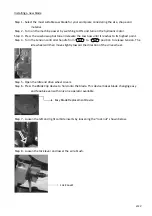
Insert
the
blade
into
the
left
and
right
tungsten
carbide
inserts.
The
back
and
the
sides
of
the
blade
need
to
be
touching
the
inserts
as
well
as
the
adjacent
rollers.
Step
12
‐
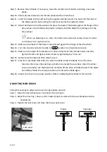
Place
the
blade
to
the
drive
wheel
and
press
the
back
of
the
blade
against
the
flange
of
the
drive
wheel.
Use
the
Blade
Clip
device
to
tightly
hold
the
blade
from
falling
out
of
the
drive
wheel.
When
saw
blade
begins
to
rotate,
the
blade
holder
will
automatically
release
the
blade
and
fall
back
to
its
original
position.
Step
13
‐
Make
sure
the
back
of
the
blade
is
also
pressed
against
the
flange
of
the
idle
wheel.
Step
14
‐
Turn
the
tension
controller
handle
to
[
]
position
to
obtain
blade
tension.
Step
15
‐
Make
sure
the
sides
of
the
blade
are
in
close
contact
with
the
carbide
inserts
and
then
tighten
the
left
and
right
carbide
inserts
by
tightening
the
“lock
nut.”
Step
16
‐
Gently
close
the
idle
and
drive
wheel
covers.
Step
17
‐
Press
the
saw
blade
start
button
to
start
the
blade.
Allow
the
blade
to
run
for
a
few
rotations
then
press
the
saw
bow
up
button
to
elevate
the
saw
bow.
Open
the
wheel
covers
and
make
sure
the
blade
has
not
fallen
off
the
drive
and
idle
wheels.
If
the
blade
has
shifted,
follow
the
same
procedure
to
reinstall
the
blade
again.
Step
18
‐
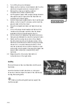
Adjust
wire
brush
to
a
proper
position.
Refer
to
Adjusting
Wire
Brush
in
this
section.
ADJUSTING
WIRE
BRUSH
Follow
these
steps
to
adjust
wire
brush
to
appropriate
position:
Step
1
‐
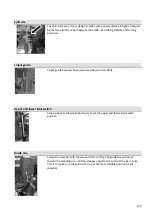
Open
the
drive
wheel
cover
and
loosen
the
lock
lever.
Step
2
‐
Adjust
the
brush
up
/
down
until
it
makes
proper
contact
with
the
saw
blade
(see
below
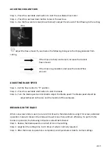
illustration).
Step
3
‐
Tighten
the
lock
lever
and
close
the
drive
wheel
cover.
Proper
Improper
Lock
Lever
Summary of Contents for SH-3026L
Page 2: ......
Page 8: ......
Page 13: ...1 5 Illustration Emergency Stop Emergency Stop Button ...
Page 15: ...1 7 Illustration Safety Labels ...
Page 20: ...2 4 FLOOR PLAN Machine top view Machine front view ...
Page 21: ...2 5 Machine front view ...
Page 22: ......
Page 32: ......
Page 48: ......
Page 50: ...5 2 ...
Page 51: ...5 3 ...
Page 52: ...5 4 ...
Page 53: ...5 5 ...
Page 54: ......
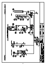
Page 55: ...6 1 Section 6 HYDRAULIC SYSTEM HYDRAULIC CIRCUIT DIAGRAM ...
Page 56: ...6 2 ...
Page 62: ......
Page 79: ...6 5 4 1 2 3 7 8 9 SH 3026L 2015 12 4 COLUMN ASSEMBLY S3026 11000 立柱組 SERIES PART LIST 10 7 ...
Page 81: ...1 4 3 2 HEIGHT CONTROL ASSEMBLY SH 3026L 2015 12 8 S3026 11400 高度控制組 SERIES PART LIST 10 9 ...
Page 83: ...SH 3026L 2015 12 8 CONTROL BOX ASSEMBLY S3026 13000 控制箱組 SERIES PART LIST 5 1 3 4 2 10 11 ...
Page 85: ...3 2 5 4 1 VISE ASSEMBLY SH 3026L 2015 12 8 S3026 22000 虎鉗組 SERIES PART LIST 10 13 ...
Page 88: ...SH 3026L 2015 12 10 S3026 30000 鋸弓組 SAW BOW ASSEMBLY SERIES PART LIST 5 13 3 4 8 10 16 ...
Page 104: ......
Page 105: ......

