


MOBILTEX® DATA LTD.
Calgary, Alberta
www.corTalk.com
TITLE:
uDL2 Configuration and Operation Guide
DOCUMENT NO.:
UDL2-MAN-001
SHEET:
13 of 28
REV:
1.07
4.3 uDL2 Configuration and Extraction
Attach the supplied USB cable between the PC and the uDL2.
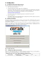
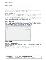
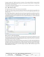
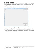
Start the configuration software by clicking on “uDL2 Configuration” shortcut in Windows start menu, under the “uDL2
Configuration Application” folder. The following screen will appear.
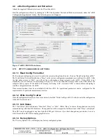
Figure 17 uDL2CONFIG Main Screen
4.3.1
uDL2 Communications and Status
4.3.1.1 Read Config From uDL2
The first step in configuring a device is to read in the current settings from the unit. Click on “Read Config From uDL2”.
The “Link Status” field will briefly show “Busy” as the current configuration parameters are read from the uDL2. After
the link status returns to “Idle”, you will see the configuration settings currently in the uDL2. If the uDL2 is not
responding or not connected, an error dialog will pop up. If it is not connected, simply connect the USB cable to the
computer and try again. If the uDL2 LCD display is showing ‘bSY’, wait until ‘USb’ is shown before attempting to
read the configuration from the uDL2.
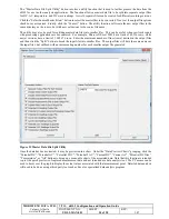
Once communications have been established with the uDL2, the operational parameters can be configured for the
requirements of a particular measurement session.
4.3.1.2 Write Config To uDL2
Once all configuration items have been set as desired, click the “Write Config to uDL2” button to write the configuration
to the uDL2 and activate it.
4.3.1.3 Link Status
The “Link Status” field will indicate “Disabled”, “Busy” or “Idle”. While “Busy” is shown, the application is actively
communicating with the uDL2 hardware. The application will not respond to further actions while “Busy” is displayed.
The uDL2 can be unplugged at any time from the USB port. However if you have changed any parameters, be sure to
write them to the uDL2 before unplugging the device.
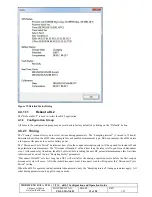
4.3.1.4 Factory Options
The “Factory Options” box will display any factory configured options.