


21
MAINTENANCE SECTION
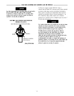
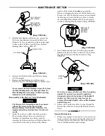
SLOT FOR TAB
(BOTH SIDES)
TAB ON INLET
RETAINER CLIP
(BOTH SIDES)
(Dwg. TPD1326)
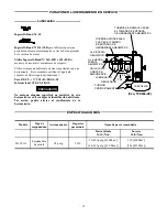
3. With the Inlet Bushing still in the vise, remove the
Tilt Valve Seat Retainer (1G) and Tilt Valve Seat
Support (1F). Use a hooked tool with no sharp edges
to remove the Tilt Valve Seat (1E) from the Inlet
Bushing. Refer to Dwg. TPD1327.
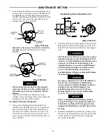
TILT VALVE STEM
HOOKED TOOL
(Dwg. TPD1327)
4. Remove the Tilt Valve (1D) and Tilt Valve Spring
(1C) if damaged.
5. Remove the Inlet Bushing Seal (1B) and Inlet
Retainer Clip (27) if damaged. Remove Washer (1A).
Do not remove the Inlet Bushing Screen (20A) from
the Inlet Bushing unless it is damaged. Clean the
Inlet Bushing Screen by using a suitable cleaning
solution in a well ventilated area.
Disassembly of the Reverse Valve Mechanism
The Reverse Valve Assembly cannot be removed
without first removing the Forward and
Reverse Buttons (4A) and (4B). Therefore, it is
important that the procedure below be followed
exactly.
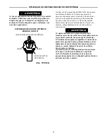
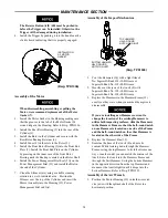
1. Notice the notches on either side of the partition.
These notches indicate the correct location for
insertion of a thin--bladed screwdriver used for
removing the Forward and Reverse Buttons. Insert the
screwdriver between the partition and the Button
which is fully extended.
Gently
pry against the
Button to disengage the detent so that the Button can
be removed. After the Button is removed, reach inside
the Housing and rotate the Reverse Valve to extend
the remaining Button. Repeat
the above procedure
for the remaining Button. Refer to Dwg. TPD1328.
(Dwg. TPD1328)
REMOVAL OF
FORWARD/
REVERSE
BUTTONS
2. Insert thumb into the front of the Housing and push
down
on the Reverse Valve so that it can be removed
through the bottom of the handle. Refer to Dwg.
TPD1329.
REVERSE
VALVE
(Dwg. TPD1329)
Do not try to remove the Reverse Valve by pushing
upward. It can only be removed by pushing it
downward and out of the bottom of the handle. If
the Reverse Valve does not come free, tap the
bottom of the handle lightly with a rubber hammer
until it drops out.
3. Remove the Top Reverse Valve O--ring (3A) and the
Bottom Reverse Valve O--ring (3B) from the Reverse
Valve.
ASSEMBLY
General Instructions
1. Whenever grasping a tool or part in a vise, always use
leather--covered vise jaws to protect the surface of the
part and help prevent distortion. This is particularly
true of threaded members and housings.
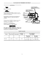
Summary of Contents for IR-C2131
Page 27: ...27...
Page 28: ...0402...