CORNING SpiderCloud SCRN-340 Hardware Installation Manual Download Page 14

14

Select the Radio Node Location

Radio nodes can be installed in a wide range of locations including walls, ceilings, and spaces above the 
ceiling. Follow the installation guidelines for selecting appropriate mounting locations for the unit. When 
mounting a radio node vertically, align the bottom-side fins vertically for superior cooling. 

Refer to the 

E-RAN Deployment Planning Guide

 for information about mounting positioning and the affects 

on cellular coverage. Always consult local codes about mounting and wiring SpiderCloud Wireless equipment.
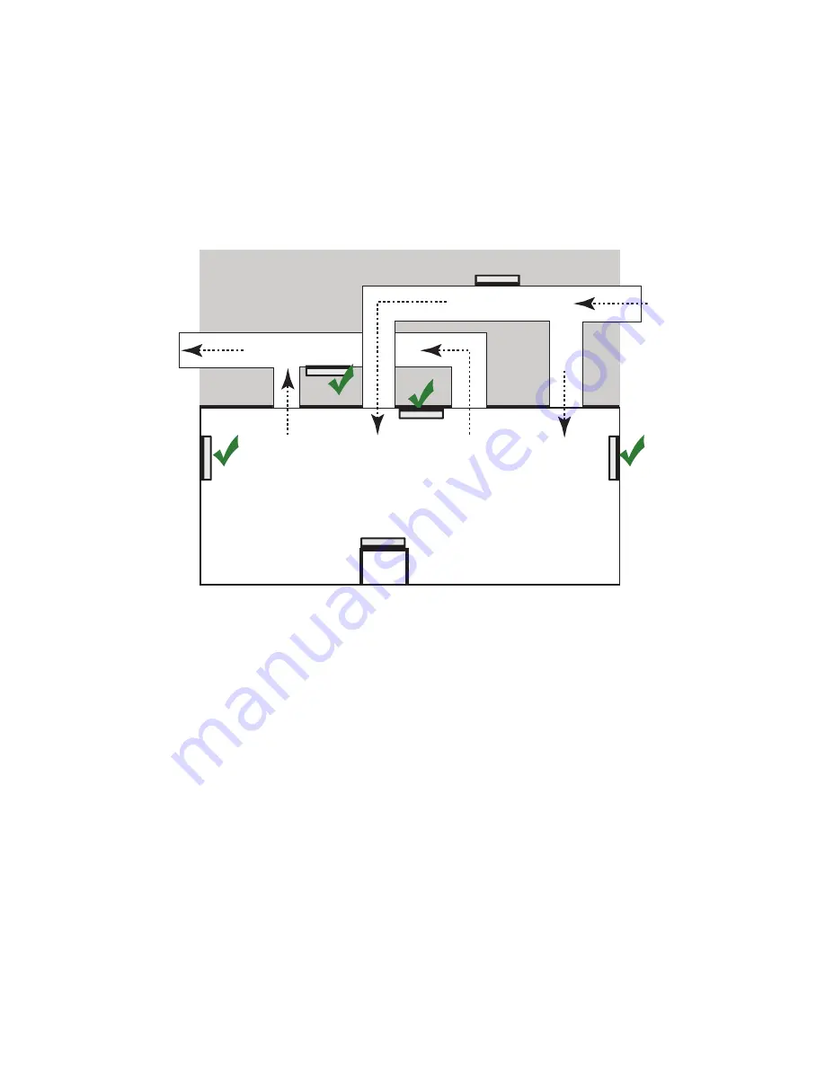
 

Figure 10 

Radio Node Locations

When possible, locate radio node units at least 6 meters (20 feet) from an external wall. This distance 
maximizes indoor coverage and minimizes RF leakage outside the building. Refer to the

 E-RAN Deployment 

Planning Guide for Dual-Mode Systems 

and 

E-RAN Deployment Planning Guide for LTE Systems 

for 

more information about 

radio node

 placement.

When mounting near a wall or other obstruction, orient the mounting bracket such that the transmit 
antenna faces towards the coverage area and faces away from the wall. Refer to 

 Bracket Mounting and 

Cabling Guidelines

 on page 15 for more information.

Installation and Mount Bracket Assembly

The radio node slides into one of two brackets for ceiling or wall mounting:

a quarter-inch (0.64 centimeter) deep for cabling through a surface such as a wall or ceiling

a 1.25 inch (3.18 centimeters) deep for exposed cabling along a hard surface such as brick or cinder 
block

Dead / Non-Circulating

Airspace

Living / Working Space of a Typical

Commercial Building

Drop Ceiling

Wall

Forced-Air Supply

Forced-Air Return

X

X

DRAFT

Summary of Contents for SpiderCloud SCRN-340

Page 1: ...SpiderCloud Radio Node SCRN 340 Hardware Installation Guide Part number DOC SCRN 340 HW 01 Rev 1 DRAFT Published xxx 2018 D R A F T...

Page 2: ...ign and structure of individual programs and the Documentation are protected by United States and foreign copyright and trade secret laws Customer agrees not to reproduce disclose alter provide or oth...

Page 3: ...14 Installation and Mount Bracket Assembly 14 Bracket Mounting and Cabling Guidelines 15 Typical Radio Node Mounting Options 15 Installing the Radio Node 15 Installing the Radio Node Method 1 16 Inst...

Page 4: ...4 D R A F T...

Page 5: ...CRN 340 supports 2x2 MIMO with a peak transmit power of 24 dBm per transmitter or 27 dBm per band When used with 20 MHz channel bandwidth each LTE carrier supports a peak downlink rate of 150 Mbps and...

Page 6: ...Model Description Antenna Type SCRN 340 02041314 Carrier 1 Band 13 or Band 14 Carrier 2 Band 25 or Band 66 Internal SCRN 340 02041314 EQ Carrier 1 Band 13 or Band 14 Carrier 2 Band 25 or Band 66 Exter...

Page 7: ...rdware Installation Guide 7 Radio Node System Isometric Top View and Bottom View The following drawings display an isometric top and bottom views of the radio node Figure 2 Radio Node Top View Figure...

Page 8: ...as Both models contain one internal network listen antenna Figure 4 shows the location of the LTE antennas Figure 4 Antenna Band Locations Figure 5 shows the radio node with external antennas This vie...

Page 9: ...OW 3G and AES air interface encryption Security Secure boot and secure key storage using Trusted Platform Module TPM functions IPsec tunneling to services node X 509 certificate based authentication E...

Page 10: ...standards Table 3 Bracket Specifications 0 25 Inch Bracket Dimensions Height 1 57 cm 6 2 in Width 1 3 cm 5 1 in Depth 0 64 cm 0 25 in Weight 0 17 kg 5 8 oz 1 25 Inch Bracket Dimensions Height 1 57 cm...

Page 11: ...nection has been established Activity Yellow blinking indicates data activity Figure 6 Ethernet Port EMC Radio FCC FCC Part 15B Class A FCC Part 15 Class A FCC Part 24 FCC Part 27 FCC 47 CFR 1 1307 b...

Page 12: ...rts Gigabit Ethernet connection and the PoE switch should support Gigabit Ethernet port The radio node will not boot up with a Fast Ethernet PoE switch Per IEEE 802 3at use standard Cat 5e or better t...

Page 13: ...injector to a radio node Step 1 Attach the injector power cord to a power source Step 2 Connect an unpowered Ethernet cable from a switch to the IN port on the injector Step 3 Connect an Ethernet cab...

Page 14: ...s RF leakage outside the building Refer to the E RAN Deployment Planning Guide for Dual Mode Systems and E RAN Deployment Planning Guide for LTE Systems for more information about radio node placement...

Page 15: ...trock or plasterboard on the wall or ceiling Mud or plaster ring Secure the universal mount bracket directly on the wall or ceiling as above with a 3 1 4 inch 8 25 centimeter mud or plaster ring betwe...

Page 16: ...1 Use this method with the quarter inch bracket when routing the Ethernet cable through an opening where the bracket will be mounted To route the cable directly and mount the radio node Step 1 Cut a h...

Page 17: ...e screw holes are sized for an M4 10 or larger screw Ensure the screws have a snug fit onto the studs sheetrock anchor or other material you are bolting onto and that you match the screw head with the...

Page 18: ...enly and mount the radio node Step 1 With two user provided screws attach the mount bracket assembly to a wall or ceiling The screw holes are sized for an M4 10 or larger screw Ensure the screws have...

Page 19: ...stallation Step 1 Attach a padlock or cable tie wrap into the provided slot to secure the unit to the mount bracket Figure 16 Padlock and Lock Holes Step 2 The radio node boots up and attempts to conn...

Page 20: ...Wireless radio nodes Refer to the SpiderCloud OS SCOS Administrator Guide for more information about the services node DHCP server configuration 2 The server responds with the IP addresses of the rad...

Page 21: ...the initial state on startup The radio node bootup is controlled by firmware in this state This state should be very short lived and should transition to the next state immediately 1 Software Initial...

Page 22: ...ations The radio node moves to the next state State 6 when it establishes connectivity with the service node Failure to start the operating system This normally points to a software build issue Please...

Page 23: ...cribes key features of the system and provides specifications for the services and radio nodes The SpiderCloud Feature Description provides high level descriptions of the E RAN system features their i...

Page 24: ...lient and using it to remotely manage E RAN deployments The E RAN Troubleshooting Guide provides information about diagnosing and correcting problems with installing provisioning administering and mai...

Page 25: ...SpiderCloud Radio Node SCRN 340 Hardware Installation Guide 25 LTE Antenna Patterns D R A F T...

Page 26: ...LTE Antenna Patterns 26 LTE Band 66 Frequency 2145 MHz Peak Gain 4 10 Dbi Frequency 2145 MHz Peak Gain 2 63 Dbi 0 Front 90 Up 90 0 Up D R A F T...

Reviews: