background image

STANDARD RECOMMENDED PROCEDURE 003-737 | ISSUE 4 | MAy 2015 | PAGE 22 OF 25

Step 1: 

Locate the feeder fiber port to be connected. 

Lower the laser safety shutter and clean the 

adapter using a dry process (Figure 32).

Step 2: 

Verify with a power meter that the power is off to 

the feeder fiber port to be connected. If power 

to that port is on, turn it off at the central office 

before proceeding.

Figure 32

In this application, making connections with the feeder power on may destroy the connector.

Step 3: 

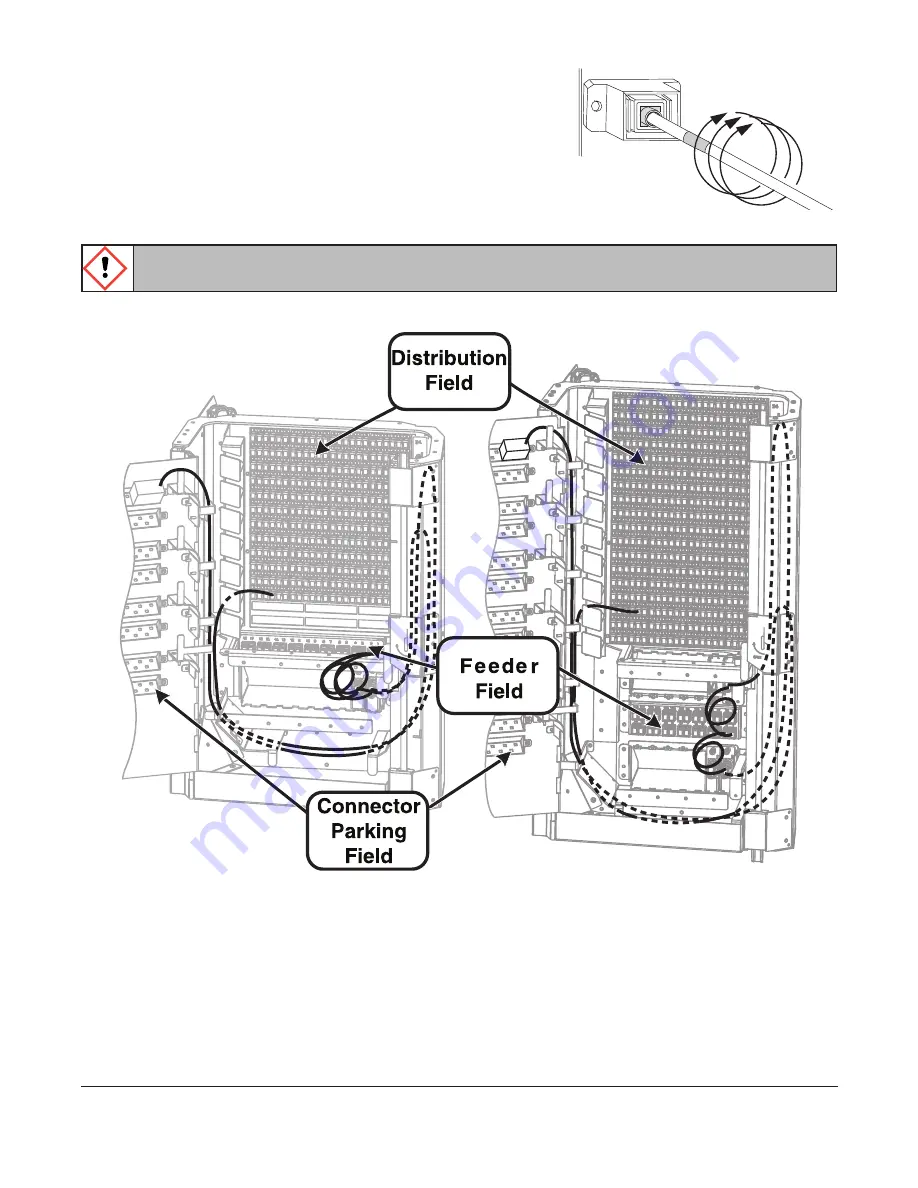
Route the connectorized splitter input fiber to the appropriate feeder port (Figure 33).

Figure 33

Step 4: 

Remove the connector dust cap. Clean the connector end-face using a dry process, 

such as with a cleaning cassette per your company’s cleaning procedures. Mate the 

connector into the port.

Step 5: 

Record the connector information on the label provided on the front door in the 

feeder section of the label.

Step 6: 

Power may now be turned on to the newly connected feeder port.

Cleaning stick

KPA-0705

KPA-0684

Summary of Contents for OptiTect EVO-707-EN

Page 1: ...the Enclosure into a Rack 8 6 3 Mount the Enclosure on the Floor 8 7 Accessing the Enclosure 10 8 Grounding the Enclosure 10 9 Managing Fiber 11 9 1 Field installed Unconnectorized Feeder and Distribu...

Page 2: ...The door can be locked with a 216B tool and padlock The standard configuration is one connectorized distribution and one connectorized feeder cable preinstalled and attached to the internal housings 1...

Page 3: ...nd 10 in on each side of the enclosure to enable the door to open fully The installing company should obtain rights of way from property owners and permits or other approvals from public authorities p...

Page 4: ...urations required for your application the following tools may be required to install the enclosure Drill and drill bits Lint free wipes Appropriate hardware if wall mounting for the wall mount surfac...

Page 5: ...er and distribution cable strain relief kit Additional Container Contents for Field splice Applications Splice trays number of trays included depends upon configuration Figure 2 Cable Entry Ports Slac...

Page 6: ...t the stabilizers are extended and firmly positioned before Lifting Avoid overhead obstructions or power lines when lifting WARNING The enclosure is heavy and requires two people to maneuver it Observ...

Page 7: ...in above the floor Ensure the bracket is level and secured to the wall to support the weight of the enclosure Step 3 Attach the wallmount mounting brackets to the rear of the enclosure as shown in Fig...

Page 8: ...lation pad installed between pedestal base and floor 1 Ground wire Step 1 Determine the cabinet location in your application per the installation plan Step 2 Determine the type of installation for flo...

Page 9: ...re for your application Step 6 Assemble the cabinet to the pedestal by fully securing the four 10 washers and self locking nuts provided Step 7 Reattach the front access panel Step 8 Replace grounding...

Page 10: ...misplacing them during the rest of the work operations Step 2 After removing the ground strap lift the door free of the hinges Set the door aside Step 3 When work operations are complete reverse these...

Page 11: ...adapter fields 9 2 Preinstalled Connectorized Feeder And Distribution Cable Option When the enclosure is ordered with the fully connectorized cable configuration the Feeder cable F1 will be mated in t...

Page 12: ...pre routed at the factory and stored for splicing 10 1 Feed Cable into Enclosure CAUTION Fiber optic cable is sensitive to excessive pulling bending and crushing forces Consult the cable specificatio...

Page 13: ...rovided with the cable Enclosure Capacity Distribution Cable s F2 Feeder Cable s F1 144 fibers 9 5 feet 10 5 feet 288 fibers 10 feet 11 feet 432 fibers 10 5 feet 11 5 feet Table 2 Cable Sheath Removal...

Page 14: ...h of Braided Tubes Required Figure 15 A B C F1 A B C F2 KPA 0897 Route large diameter cable as shown Route smaller diameter cables as shown OR C B Top View of Splice Compartment B D Top of Cabinet 1 5...

Page 15: ...ied in the braided tubing kit to the end of the fiber s with the electrical tape Figure 16 Figure 16 Step 3 Push the braided tubing over the rod Figure 17 Figure 17 Step 4 Slide tubing toward the cabl...

Page 16: ...Figure 21 Step 8 Secure the other end of the braided tubing Figure 22 Cut off the plastic rod Wrap electrical tape around the end of the braided tubing IMPORTANT Approximately 48 in of ribbon matrix s...

Page 17: ...8 in wrench to drive the teeth on the upper plate into the sheath Step 4 Wrap the grounding connector and split portion of the sheath with a few wraps of vinyl tape Step 5 Attach the ring terminal of...

Page 18: ...event the retention grip from overlapping the ground hardware Step 2 If there is a central member present install the central member restraint clip as shown in Figure 25 Trim the central member flush...

Page 19: ...curs in the bottom splice tray in the splice housing with Distribution splicing in subsequent trays above Two sub units jacketed or braided tubing with three 12 fiber ribbons per sub unit can be strai...

Page 20: ...the connectorized pigtails to the Feeder or Distribution cable in accordance with the instructions provided with the splicing equipment Step 5 Return and route the fibers within the splice tray securi...

Page 21: ...13 Connecting Splitter Input Fibers to Feeder Cable The splitter module is designed with bend optimized fiber Do not uncoil the slack of the input fiber except when necessary to reach the appropriate...

Page 22: ...is application making connections with the feeder power on may destroy the connector Step 3 Route the connectorized splitter input fiber to the appropriate feeder port Figure 33 Figure 33 Step 4 Remov...

Page 23: ...e using a dry process Mate the splitter output fiber connector to the distribution connector Step 4 Route the splitter output fiber slack as shown on the fiber routing label on the inside of the enclo...

Page 24: ...rule twice with a lint free wiping material moistened with isopropyl alcohol Then wipe across the end of the ferrule Step 3 Repeat previous step with a dry wipe If necessary it is also possible to acc...

Page 25: ...do not exceed the minimum bend radius Check cables for unnecessary strain for crimping or crushing at entries and exits and for damage Check unit record labels to make sure all are clear and accurate...

Reviews: