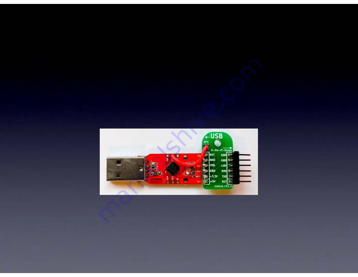
Connecting your ArduTouch
to your computer
USB-Serial adapter cable
Ones available from Cornfield Electronics look like this:
You will need to download and install a driver
for your Operating System (Windows, MacOS, or Linux):
<https://www.silabs.com/products/development-tools/software/usb-to-uart-bridge-vcp-drivers>
<https://cornfieldelectronics.com/cfe/products/buy.php?productId=usbcable>
Summary of Contents for ArduTouch
Page 1: ...ArduTouch Music Synthesizer Assembly Instructions rev C 27 Feb 2019 ...
Page 3: ...Learn To Solder download for free at http mightyohm com soldercomic ...
Page 8: ...All of the parts Some parts are inside of this battery pack ...
Page 9: ...The board we ll solder the parts to ...
Page 11: ...R1 this is where it goes ...
Page 12: ...R1 Brown Black Orange not Brown Black Red ...
Page 13: ...R1 ...
Page 14: ...wires coming out from parts are called leads they lead to the part ...
Page 15: ...R1 this is how it will look before inserting it into the board ...
Page 16: ...these are pads ...
Page 17: ......
Page 18: ......
Page 19: ...R1 inserted into the board ...
Page 20: ...How to hold a soldering iron Like a pencil held from underneath ...
Page 22: ...3 Safety Tips ...
Page 23: ...Safety Tip 1 Hot When you touch the tip you will let go quickly every time ...
Page 24: ...Safety Tip 2 Lead Pb is toxic But it easily washes off your hands with soap and water ...
Page 25: ...Safety Tip 3 coming soon ...
Page 26: ...2 secrets to good soldering ...
Page 28: ......
Page 29: ......
Page 31: ......
Page 32: ...Secret 2 Keep hot tip down 1 second for solder to flow ...
Page 33: ...Now ...
Page 35: ...Cutting with the tip of the wire cutter gives you more control ...
Page 36: ...Safety Tip 3 Hold or cover the lead or it will fly into your eye ...
Page 37: ...No wire sticking out ...
Page 39: ...One part at a time ...
Page 40: ...Till all the parts are soldered ...
Page 41: ...And it will look like this when you re done ...
Page 42: ...Let s start ...
Page 43: ...If you haven t done so already solder R1 brown black orange ...
Page 45: ...U1 microcontroller socket proper orientation ...
Page 46: ...U1 microcontroller socket inserted correctly ...
Page 47: ...U1 microcontroller socket bend pins down on two corners and solder all 28 leads to the board ...
Page 49: ...C1 C2 C4 C5 ...
Page 50: ...C3 C8 100uF ...
Page 51: ...C6 C7 1uF ...
Page 52: ...C3 C8 100uF ...
Page 53: ...C3 C8 Long Lead ...
Page 54: ...C3 C8 100uF soldered to board ...
Page 55: ...C6 C7 1uF ...
Page 56: ...C6 C7 Long Lead ...
Page 57: ...C6 C7 1uF soldered to board ...
Page 58: ...LED1 LED2 LED3 Long Lead We ll use them for the speaker ...
Page 59: ...LED1 LED2 LED3 Green Red Blue soldered to board ...
Page 60: ...J1 short leads long leads ...
Page 61: ...J1 Short leads into board short leads go into the board long leads sticking out from board ...
Page 62: ...J1 ...
Page 65: ...X1 The orientation of X1 does not matter Note X1 may be yellow or blue ...
Page 67: ...U2 When chips are new their pins are bent out ...
Page 68: ...U2 We need the pins bent straight and parallel Use your work table to gently bend the leads ...
Page 69: ...Gently bend leads so they re straight and parallel U2 ...
Page 70: ...U2 audio amp chip proper orientation ...
Page 71: ...U2 inserted correctly ...
Page 72: ...U2 bend pins down on two corners and solder all 8 leads to the board ...
Page 73: ...U2 soldered to board ...
Page 74: ...R10 volume control When new the pins point straight down ...
Page 75: ...R10 volume control We need to bend them out a little to fit into the board ...
Page 77: ...J3 headphone output jack ...
Page 78: ...U1 microcontroller ...
Page 81: ...U1 microcontroller These pins must be straight and parallel ...
Page 82: ...U1 microcontroller proper orientation ...
Page 86: ...R11 R12 potentiometers ...
Page 87: ...R11 R12 potentiometers ...
Page 88: ...Speaker ...
Page 89: ...Speaker Some kits have a speaker that looks like this ...
Page 90: ...Speaker We ll add leads to the speaker from the LEDs ...
Page 91: ...Speaker Tin one side of each lead i e cover with thin film of melted solder ...
Page 92: ...Speaker Solder one lead to speaker Notice the correct place to solder the wire ...
Page 93: ...Speaker Solder next lead to speaker Notice the correct place to solder the wire ...
Page 95: ...Speaker Insert speaker into board and solder both leads to board ...
Page 98: ...Done ...
Page 99: ...Let s make noise ...
Page 104: ...Arduino First Download and install the Arduino software http arduino cc ...
Page 113: ...Arduino Your Arduino software is now ready to program your ArduTouch ...
Page 114: ...Arduino You can open an ArduTouch synth sketch from File Open I opened Arpology here ...
Page 115: ...Arduino With the USB Serial cable connected to your ArduTouch board press the Upload button ...
Page 118: ...Let s make new noise ...


