UCR 700 Series Continuous Flow Icemaker Installation/ServiceManual
Publication Number: 630460154
- 5 -
© 2001-2012, IMI Cornelius Inc.
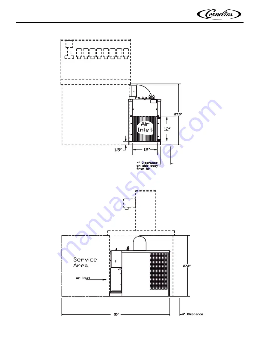
Figure 1. Clearance Requirements
Page 1: ...OUS FLOW ICEMAKER Installation Service Manual Release Date May 2001 Publication Number 630460154 Revision Date January 12 2012 Revision C Visit the IMI Cornelius web site at www cornelius com for all...
Page 2: ...rvice required by or loss or damage resulting from any of the following occurrences including but not limited to 1 other than normal and proper use and normal service conditions with respect to the Pr...
Page 3: ...Data 3 Specification Chart 4 Installation 6 Pre Installation 6 Freight Damage Claim 6 Counter 6 Electrical 6 Drain 6 Installation 6 Initial Start up Checks and Adjustment Instructions 8 Guide to servi...
Page 4: ...Replace Gearmotor Assembly 15 Auger and Extruding Head Removal 16 Installation and Shaft Seal Replacement 16 Upper Nut and Bearing Assembly 16 To Replace Bearing 17 Electrical Checkout 17 Overload Ch...
Page 5: ...minor or moderate injury or equipment damage SAFETY TIPS Carefully readandfollowall safety messagesinthismanualandsafety signsontheunit Keepsafety signsin goodconditionandreplace missingordamageditem...
Page 6: ...the power is off to the unit before any work is performed Failure to disconnect the power could result in serious injury death or equipment damage CAUTION Always be sure to keep area around the unit c...
Page 7: ...or right side and the rear of the machine for air exaust CLAIMS INSTRUCTIONS Claims In the event of shortage notify the carrier as well as IMI Cornelius immediately In the event of damage notify the...
Page 8: ...rain Overflow Line Located at rear of the Unit 3 8 inch Flexible Tubing Ambient Operating Temperature 40 F to 100 F Electrical Unit Electrical Rating 115 VAC 60 Hz 15 6 Amps Single Phase Recommended E...
Page 9: ...UCR 700 Series Continuous Flow Icemaker Installation ServiceManual Publication Number 630460154 5 2001 2012 IMI Cornelius Inc Figure 1 Clearance Requirements...
Page 10: ...of achieving a satisfactory resolution to the claim COUNTER 1 A flat and level counter space sufficiently strong to support the weight of the Dispenser and the Icemaker The Icemaker may be installed...
Page 11: ...vel adjustment bolts located on the lower front of the Icemaker D Install the locking bolt on the lower front of the icemaker E Connect drain power and water 6 Install transport tube A Insert the ice...
Page 12: ...ase float and Icemaker will restart Keep water in reservoir at level line while the Icemaker is in operation See Figure 3 Low Water Safety Control Adjust magnet by bending magnet arm as needed to shut...
Page 13: ...tize using household liquid bleach 50 ppm chlorine Mixture 1 fluid ounce per gallon room tempera ture water 2 minute exposure time 10 Sanitize auger assembly and ice transition tube in a sink using sa...
Page 14: ...valve seat which seals the water off SeeFigure 3 Before the water inlet is sealed the safety switch is operated In the event of a water failure the float would drop down and operate the safety switch...
Page 15: ...3 Remove the 2 screws anchoring the water level safety switch to the bottom of the water level control mounting bracket REFRIGERATION SYSTEM NOTE Thermostatic Expansion Valve No Adjustment 10 Lbs Dis...
Page 16: ...ctions replace valve When replacing valve be sure to bleed refrigerant gas from low side port so as not to lose refrigerant oil Use general refrigerant system practices when replacing and recharging u...
Page 17: ...nnect power to unit and remove one wire from switch Connect both leads of your ohmmeter to the Bin Control Switch terminals With control bulb at room temperature ohmmeter should read Closed Circuit No...
Page 18: ...s to automatically shut off the motor in the event of a mechanical bind of the transmission an overload condition within the evaporator or an electrical malfunction It does this by sensing amperage dr...
Page 19: ...be open 2 Check between 3 and 4 on relay if no continuity replace the relay Figure 7 Gearmotor Assembly TO REPLACE GEARMOTOR ASSEMBLY 1 Disconnect the icemaker from the electrical power source 2 Disc...
Page 20: ...2 Place rubber coated ceramic seal important ceramic face up over output shaft and push down until seal nest in recess of shaft seal mount lubricate rubber on ceramic seal with rubber lubricant 3 Pla...
Page 21: ...vent shocks 3 Disconnect the compressor terminal wires OVERLOAD CHECK Using a volt ohmmeter check the continuity across the overload contact 1 and 3 If none wait for unit to cool down and try again If...
Page 22: ...has several safety and control devices incorporated into its design WARNING None of the below described devices should ever be bypassed to allow the unit to function The safety and control system shut...
Page 23: ...UCR 700 Series Continuous Flow Icemaker Installation ServiceManual Publication Number 630460154 19 2001 2012 IMI Cornelius Inc...
Page 24: ...UCR 700 Series Continuous Flow Icemaker Installation Service Manual 2001 2012 IMI Cornelius Inc 20 Publication Number 630460154 Figure 13 Wiring Diagram...
Page 25: ...UCR 700 Series Continuous Flow Icemaker Installation ServiceManual Publication Number 630460154 21 2001 2012 IMI Cornelius Inc Figure 14 Wiring Diagram 240V...
Page 26: ...UCR 700 Series Continuous Flow Icemaker Installation Service Manual 2001 2012 IMI Cornelius Inc 22 Publication Number 630460154...
Page 27: ...e areas of checkout THE COMPRESSOR WILL NOT RUN A No voltage to the com pressor terminals B Low voltage C Problems in the com pressor electrical cir cuit A Check circuit B Below 90 of name plate rated...
Page 28: ...Bin 2 630000806 Panel Top 12 630200868 Brkt Chassis Alignment Fnt 3 13 630200876 Brkt Bin Alignment Rear 4 14 630200735 Cover Elec Box 5 630000808 Panel Left Hand 15 630250094 Line Water Inlet 6 6300...
Page 29: ...0 2 630000741 Elbow Ice Chute 3 630250106 Tube Ice Transfer 4 630900564 O Ring 4 234 I D 5 630900608 Head Extruder 6 638090213 Auger 7 638090219 Bearing Nylon 8 638090220 Bearing Delrin 9 638090211 00...
Page 30: ...t Capacitor 115V 161998015 Relay Start Capacitor 230V 7 164083001 Hex Nut No 6 32 8 630000599 Wrap 9 630200166 Strap Capacitor 10 630900111 Thread Cutting Screw Phil Pan Hd No 8 32 By 3 4 In Long 11 6...
Page 31: ...168833002 Washer 4 311462000 Machine Screw Hex Hd 5 16 18 By 1 2 In Long 5 630000651 Evaporator Tube 6 30201088 Bracket Front End 7 630900128 8 638005406 Shield Motor 9 638031027 O Ring 10 638090051 S...
Page 32: ...5 630900635 Machine Screw Hex Hd 1 4 20 By 1 3 4 In Long 6 638001662 Insulator Switch 7 638003924 Switch 8 638007009 10 Screw No 6 By 1 1 4 In Long 9 638007264 02 Tinnerman Nut 10 638007308 01 Washer...
Page 33: ......
Page 34: ...IMI Cornelius Inc www cornelius com...