


Copyright © 2021 CoreTigo Ltd.
TigoStarter K22
User Manual
Page
18
of
43
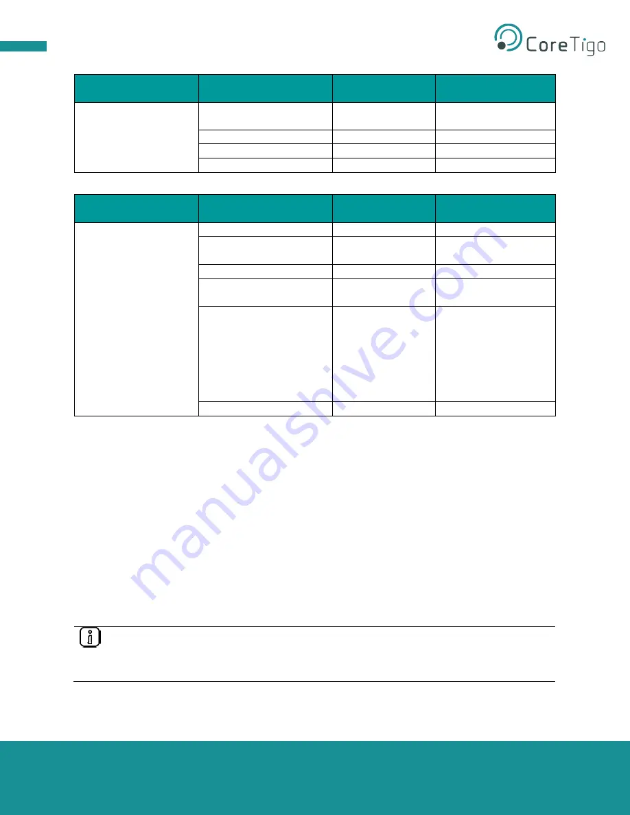
Wireless Track Status
LED
LED Color
State
Indication
WT1 - WT3
Green
On
Track Operational Mode
/ Service Mode
Yellow
On
Track Inactive
Red
Blinking
Track Error
Green
Off
Track Off
Table 9
– TigoMaster 2TH Supply Voltage Status LEDs
Wireless Port Status
LED
LED Color
State
Indication
WP01 - WP16
Green
On
Port Operational
Green
Blinking
Pairing Successful and
Communication Ready
Yellow
Blinking
Port Ready
Red
Blinking
Port Communication
Lost
Red
On
Port Errors (Pairing
Timeout, Pairing Wrong
Slot Type, Revision
Fault, Compatibility
Fault, Serial Number
Fault, Process Data
Fault, Cycle Time Fault)
Grey
Off
Port Inactive
Table 10
– TigoMaster 2TH Supply Voltage Status LEDs
3.2.3. Software System Level
– TigoEngine Software Tool
The TigoEngine software tool allows users to efficiently set up IO-Link Wireless masters and devices, such
as the TigoMaster 2TH IO-Link Wireless Master and IO-Link Wireless sensors and actuators. Once
installed, users may configure, test, and evaluate IO-Link Wireless devices.
See section 4 for further details on the TigoEngine software tool.
3.3. Setup and Configuration
Follow the steps below to set up and configure the following hardware components:
•
TigoMaster 2TH IO-Link Wireless Master
•
IO-Link Wireless TigoBridge
For information on the setup and configuration of software components, see section 4 of this user manual
on the use of the TigoEngine software tool, and see section 5 on establishing a local PLC connection.
Note:
The devices and cables described below are part of the kit and supplied by CoreTigo Ltd.
Other mentioned items, such as the PLC, PC, on-premise server, and IO-Link devices such
as sensors and actuators are not provided by CoreTigo Ltd. and considered user property.


