Copley Controls Corp. Xenus XTL User Manual Download Page 22

Operational Theory 


Xenus XTL User Guide 

22 

Copley Controls Corp. 

2.5.4: Position Mode and Position Loop 

Position Loop Diagram 

The amplifier receives position commands from the digital or analog command inputs, over the 
CAN interface or serial bus, or from the CVM Control Program. When using digital or analog 
inputs, the amplifier's internal trajectory generator calculates a trapezoidal motion profile based on 
trajectory limit parameters. When using the CAN bus, serial bus, or CVM Control Program, a 
trapezoidal or S-curve profile can be programmed. The trajectory generator updates the 
calculated profile in real time as position commands are received.  
The output of the generator is an instantaneous position command (limited position). In addition, 
values for the instantaneous profile velocity and acceleration are generated. These signals, along 
with the actual position feedback, are processed by the position loop to generate a velocity 
command. 
To bypass the trajectory generator while in digital or analog position modes, set the maximum 
acceleration to zero. The only limits in effect will now be the velocity loop velocity limit and the 
current limits. (Note that leaving the maximum acceleration set to zero will prevent other position 
modes from operating correctly.) 
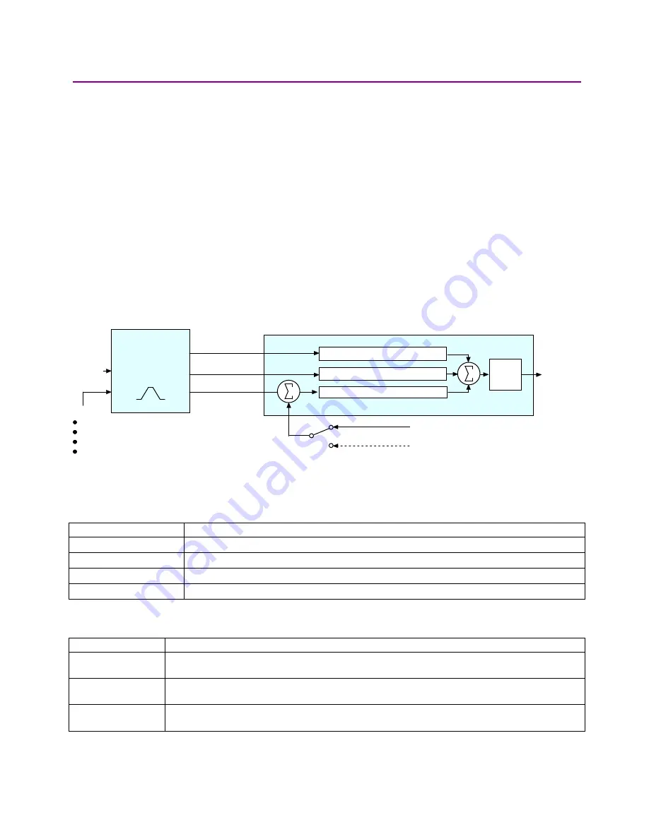
The following diagram summarizes the position loop. 

Target
Position

Velocity
Command

Trajectory

Ge ne rator

Position Loop

Feedback

Limits:

Max velocity
Max accel
Max decel
Abort decel

Position Proportional Gain (Pp)

Velocity Feed Forw ard (Vff)

Acceleration Feed Forw ard (Aff)

Profile Acceleration

Profile Velocity

Limited Position

+

+

-

+

+

Gain

Multiplier

from motor encoder or resolver

from optional position encoder (on load)


Trajectory Limits  

In position mode, the trajectory generator applies the following user-set limits to generate the 
motion profile. 

Limiter Description 

Maximum Velocity 

Limits the maximum speed of the profile. 

Maximum Acceleration 

Limits the maximum acceleration rate of the profile.  

Maximum Deceleration 

Limits the maximum deceleration rate of the profile.  

Abort Deceleration 

Specifies the deceleration rate used by the trajectory generator when motion is aborted.  

Position Loop Inputs From the Trajectory Generator 

The position loop receives the following inputs from the trajectory generator. 

Input Description 

Profile Velocity 

The instantaneous velocity value of the profile. Used to calculate the velocity feed forward 
value. 

Profile Acceleration  The instantaneous acceleration/deceleration value of the profile. Used to calculate the 

acceleration feed forward value. 

Limited Position 

The instantaneous commanded position of the profile. Used with the actual position feedback to 
generate a position error. 

Summary of Contents for Xenus XTL

Page 1: ...Xenus XTL User Guide P N 95 00875 000 Revision 3 June 2008...

Page 2: ...Xenus XTL User Guide This page for notes...

Page 3: ...ut 47 3 11 Encoder Power Supply Output 47 3 12 Primary Encoder Inputs 47 3 13 Analog Encoder Inputs 47 3 14 Hall Switch Inputs 48 3 15 Resolver Interface 48 3 16 Multi Mode Port 48 3 17 Serial Interfa...

Page 4: ...Thermal Considerations 159 C 1 Operating Temperature and Cooling Configurations 160 C 2 Heatsink Mounting Instructions 162 D Xenus Filter 163 D 1 Overview 164 D 2 XTL FA 01 Edge Filter Specifications...

Page 5: ...tion on Copley Controls Software can be found at http www copleycontrols com Motion Products Software index html Comments Copley Controls Corporation welcomes your comments on this manual For contact...

Page 6: ...sure to safeguard against unexpected motion Failure to heed this warning can cause equipment damage injury or death Using CME 2 or serial commands may affect or suspend CAN operations DANGER When ope...

Page 7: ...y Controls Corp 7 Revision History Revision Date DECO Comments 1 December 2007 16236 Initial release 2 February 2008 16714 Updated Multi Mode Port Interface Diagram p 66 3 June 2008 17111 Updated Web...

Page 8: ...About this Manual Xenus XTL User Guide 8 Copley Controls Corp This page for notes...

Page 9: ...Copley Controls Corp 9 CHAPTER 1 INTRODUCTION This chapter provides an overview of the Copley Controls Xenus XTL amplifier Contents include Title Page 1 1 Amplifier 10 1 2 CME 2 11 1 3 CMO CML 11...

Page 10: ...and position profiling interpolated motion and homing operations Multiple drives can be tightly synchronized for high performance coordinated motion As a node on a DeviceNet network Xenus can be opera...

Page 11: ...tablish the direction of positive motion is also eliminated Motor data can be saved as ccm files Amplifier data is saved as ccx files that contain all amplifier settings plus motor data This makes it...

Page 12: ...Introduction Xenus XTL User Guide 12 Copley Controls Corp...

Page 13: ...al Power 14 2 2 Synchronizing PWM Switching Frequency 16 2 3 Commutation Modes 16 2 4 Feedback 16 2 5 Operating Modes 17 2 6 CANopen Operation 28 2 7 Limit Switches 30 2 8 Brake Operation 31 2 9 Statu...

Page 14: ...return The CAN interface is also optically isolated Deriving internal operating voltages from a separate source enables the amplifier to stay on line when the mains have been disconnected for emergen...

Page 15: ...V W MOTOR HALLS ENCODER CASE ISOLATION BARRIER 5 Vdc DC BUSS DC BUSS L2 AMPLIFIER CHASSIS CONTROL SYSTEM ENABLE IN1 SIGNAL GND SIGNAL GND SHIELD J8 J7 J1 J2 FRAME SAFETY GROUND CONTROL SIGNAL GROUND...

Page 16: ...s trapezoidal commutation mode the amplifier provides traditional six step commutation When driving a DC brush motor the amplifier operates as a traditional H Bridge amplifier 2 4 Feedback 2 4 1 Encod...

Page 17: ...urrent loop is driven directly by external or internal current commands Basic Attributes of All Control Loops These loops and servo control loops in general share several common attributes Loop Attrib...

Page 18: ...r position modes the current command is generated by the velocity loop Offset The current loop offset is intended for use in applications where there is a constant force applied to or required of the...

Page 19: ...tegral The integral of the current error is multiplied by this value Integral gain reduces the current error to zero over time It controls the DC accuracy of the loop or the flatness of the top of a s...

Page 20: ...or PWM inputs A network command CANopen DeviceNet or RS 232 Serial A Copley Virtual Motion CVM control program The amplifier s internal function generator In position mode the velocity command is gene...

Page 21: ...ve signal The error integral is the accumulated sum of the velocity error value over time Velocity Loop Gains Scalar The Enable Gains Scalar feature increases or decreases the resolution of the units...

Page 22: ...from operating correctly The following diagram summarizes the position loop Target Position Velocity Command Trajectory Generator Position Loop Feedback Limits Max velocity Max accel Max decel Abort...

Page 23: ...nd Types The amplifier can be controlled by a variety of external sources analog voltage or digital inputs CAN network CANopen or DeviceNet or over an RS 232 serial connection using ASCII commands The...

Page 24: ...voltage An example of this would be a 0 to 10 Vdc velocity command that had to control 1000 rpm CCW to 1000 rpm CW Scale would be set to 2000 rpm for a 10 Vdc input and Offset set to 5V After this a...

Page 25: ...Cycle Increasing Duty Cycle Max Max 0 PWM Input Amplifier Output 50 Duty Cycle The command can be inverted so that increased duty cycle commands negative output and vice versa 100 Duty Cycle Format Tw...

Page 26: ...control acceleration and deceleration rates When using digital or analog command inputs the trajectory generator can be disabled by setting the Max Accel limit to zero Note that when using the CAN bus...

Page 27: ...olution can be programmed for electronic gearing Quadrature Format In quadrature format A B quadrature commands from a master encoder via two inputs provide velocity and direction commands as shown be...

Page 28: ...s down at the same rate In profile velocity mode the amplifier is programmed with a velocity a direction and acceleration and deceleration rates When the amplifier is enabled the motor accelerates to...

Page 29: ...CAN Network 2 6 4 CAN Addressing A CANopen network can support up to 127 nodes Each node must have a unique and valid seven bit address Node ID in the range of 1 127 Address 0 is reserved and should o...

Page 30: ...ection is still allowed Amplifier status indicator flashes green at fast rate Warning is displayed on CME 2 Control Panel and CME 2 Control Panel limit indicator turns red Position Amplifier stops res...

Page 31: ...and Logic Supply Brake J4 p 60 2 8 2 Brake Stop Sequences Disabling the amplifier by a hardware or software command starts the following sequence of events The motor begins to decelerate at Abort Dece...

Page 32: ...own below Xenus Status Indicator CAN Status Indicator 2 9 2 Amplifier Status Indicator Operation Amplifier status indicator color blink codes are described below Color Blink Code Meaning Not illuminat...

Page 33: ...ror conditions CANopen State Machine Mode of Operation Indicator State Diagram Blinking green Pre operational 200 ms off 200 ms green Steady green Operational off green Single flash green Stopped gree...

Page 34: ...k of unexpected motion with non latched faults DANGER After the cause of a non latched fault is corrected the amplifier re enables the PWM output stage without operator intervention In this case motio...

Page 35: ...the output of the internal 5 Vdc supply used to power the feedback Resolver or analog encoder not connected or levels out of tolerance Encoder power returns to specified voltage range Feedback signals...

Page 36: ...ty error fault 2 11 2 Following Error Faults When the position error reaches the programmed fault threshold the amplifier immediately faults The following error fault can be disabled For detailed info...

Page 37: ...ter a Non Latched Following Error Fault The clearing of a non latched following error depends on the amplifier s mode of operation Issuing a new trajectory command over the CAN bus the ASCII interface...

Page 38: ...s the difference between commanded and actual velocity When the position or velocity error exceeds the programmed tracking window value a status word bit is set The bit is not reset until the error re...

Page 39: ...the digital inputs CAN interface When operating as a CANopen or DeviceNet node the amplifier takes input commands over a CAN bus CAN communications are described in CME 2 and CAN Operation p 39 Device...

Page 40: ...se Down and Quadrature A B are wired to inputs that have the HS filters and inputs with the GP filters are used for general purpose logic functions limit switches and the motor temperature sensor 2 13...

Page 41: ...or in series with a diode connected to the amplifier s internal 5 Vdc supply This design allows the outputs to be directly connected to optically isolated PLC inputs that reference a voltage higher th...

Page 42: ...some of the energy into an external regen resistor when the voltage rises too high 2 15 3 Regen Circuit Components The amplifier provides an internal transistor that is used in combination with an ex...

Page 43: ...3 7 Analog Command Input 46 3 8 Digital Inputs 46 3 9 Digital Outputs 46 3 10 Brake Output 47 3 11 Encoder Power Supply Output 47 3 12 Primary Encoder Inputs 47 3 13 Analog Encoder Inputs 47 3 14 Hall...

Page 44: ...35 A peak at 240 Vac Logic Supply Voltage 20 to 32 Vdc Logic Supply Current 500 mA maximum 3 3 Power Output Model XTL 230 18 R S XTL 230 36 R S XTL 230 40 R S Peak Current 18 Adc 12 7 Arms 36 Adc 25...

Page 45: ...not affect tuning 3 5 Regen Circuit Output Model XTL 230 18 R S XTL 230 36 R S XTL 230 40 R S Continuous Power 2 kW 4 kW Peak Power 5 kW 10 kW Minimum Resistance 30 15 Minimum Resistor Wattage 25 W 50...

Page 46: ...e as pull up or pull down to internal 5 Vdc Input Voltage Range General Purpose High speed 0 V 28 Vdc 0 V 12 Vdc Logic Low Input Voltage 1 35 Vdc Logic High Input Voltage 3 65 Vdc Scan Time 333 Sec RC...

Page 47: ...Non isolated Signals A A B B X X Input Voltage Range 7 Vdc Differential Input Threshold 0 2 Vdc Termination Resistance 121 Maximum Frequency 5 MHz Line 20 Mcount sec Function Incremental or analog en...

Page 48: ...r for proper feedback levels Reference Max Current 100 mA Max RPM 10 000 Function Incremental or analog encoder or resolver required for sinusoidal commutation and position or velocity modes of operat...

Page 49: ...tion Control Device Under DSP 402 of the CANopen DS 301 V4 01 EN 50325 4 Application Layer Supported Modes Profile Current Velocity and Position PVT and Homing Node Address Selection 16 position rotar...

Page 50: ...22 Thermal Impedance See Thermal Considerations p 159 3 23 Mechanical and Environmental Size 7 55 in 191 8 mm X 5 57 in 141 5 mm X 2 57 in 65 3 mm Weight Without Heat Sink With Heat Sink XTL HL With H...

Page 51: ...Xenus XTL User Guide Specifications Copley Controls Corp 51 3 24 Dimensions...

Page 52: ...Specifications Xenus XTL User Guide 52 Copley Controls Corp...

Page 53: ...er and motor connections Contents include Title Page 4 1 General Wiring Instructions 54 4 2 AC Mains J1 56 4 3 Motor J2 57 4 4 Regen Resistor J3 Optional 59 4 5 Logic Supply Brake J4 60 4 6 RS 232 Ser...

Page 54: ...g connectors with power applied WARNING The connecting or disconnecting of cables while the amplifier has 24Vdc and or mains power applied is not recommended Failure to heed this warning may cause equ...

Page 55: ...this wire should be of the same gauge as the other regen resistor conductors Cable shields because of their smaller wire size must not be used as part of a safety ground system Signal Grounding The am...

Page 56: ...600 V 36 A and 40 A models 12 AWG 600 V Shielded cable required for CE compliance Wire Insertion Extraction Tool Wago 231 131 Connector and tool are included in connector kit XTL CK or XTL CA Pin Desc...

Page 57: ...lifier J1 L1 L2 J1 4 J1 1 J1 2 Filter Concepts 3F15 or equivalent used for CE compliance 4 3 Motor J2 Mating Connector Description Euro style 4 position 5 0 mm pluggable female terminal block Manufact...

Page 58: ...Guide 58 Copley Controls Corp Brushless Motor Wiring Diagram Amplifier U V W J2 A B C Brushless Motor Case Ground J2 2 J2 1 J2 3 J2 4 Brush Motor Wiring Diagram U V Brush Motor Case Ground Amplifier J...

Page 59: ...n Pin Signal Function 1 Regen DC Bus to one side of regen resistor 2 N C No connection 3 Regen Collector of regen transistor to one side of regen resistor 4 N C No connection 5 Ground Enclosure ground...

Page 60: ...Size 22 14 AWG Recommended Wire 18 AWG Wire Insertion Extraction Tool Wago 231 131 Standard connector and tool are included in connector kit XTL CK or XTL CA Pin Description Pin Signal Function 1 RTN...

Page 61: ...rial Cable Kit PN SER CK A diagram of the female connector is shown below 1 2 3 4 5 6 Pin Description Pin Signal Function 1 N C No connection 2 RxD Receive data input from computer 3 Signal ground Pow...

Page 62: ...2 CAN _L CAN_L bus line dominant low 3 CAN_Gnd Ground 0 V V 4 No connection 5 Pass though to second connector no internal connection 6 CAN_SHLD Pass though to second connector no internal connection 7...

Page 63: ...ion Manufacturer PN Wire Size 26 Position 0 1 x 0 09 High Density D Sub Male Solder Style Connector Norcomp 180 026 103L001 24 30 AWG Back shell Norcomp 979 015 020R121 Solder style connector included...

Page 64: ...uts HS Group 3 11 IN7 HS Group 3 12 IN8 HS Group 3 13 IN9 HS Group 4 14 IN10 Mode dependent See Mode Dependant Dedicated Inputs p 65 HS Group 4 15 Signal Ground Signal ground reference for inputs and...

Page 65: ...ty PWM 100 10 10 8 B B Direction Input 9 9 7 A A Pulse Input Position Pulse Direction 10 10 8 B B Direction Input 9 9 7 A A Count Up Position Up Down 10 10 8 B B Count Down 9 9 7 A A Channel A Positio...

Page 66: ...otion Controller 5 Vdc 1 K J7 OUT1 OUT2 OUT3 Signal Ground Relay Lamp Typical Output Loads Flyback diode required for inductive loads Multi Mode Port Interface Diagram J7 23 Amplifier Typical Circuit...

Page 67: ...er J7 Motion Controller 4 9 Motor Feedback J8 Mating Connector Description Manufacturer PN Wire Size 15 Position High Density D Sub Male Solder Style Connector Norcomp 180 015 103L001 24 30 AWG Back s...

Page 68: ...emperature switch May be programmed to other functions Standard speed Pull up pull down group 2 11 Encoder B Input 12 Encoder B Input 13 Encoder A Input 14 Encoder A Input Primary incremental encoder...

Page 69: ...und Signal and 5 Vdc ground 6 Digital Hall V 7 Encoder X Input 8 Encoder X Input 9 Digital Hall W 10 IN5 Motemp Motor over temperature switch May be programmed to other functions Standard speed Pull u...

Page 70: ...J8 4 J8 2 Typical Circuit 5 V 400 mA 5 Vdc 3 3 10 K 10 K Frame Gnd 5 Vdc Gnd Halls Power Case Ground U V W Hall Hall Hall Halls Amplifier J8 Analog Sin Cos Encoder Wiring Diagram J8 14 J8 13 J8 12 J8...

Page 71: ...13 J8 12 J8 1 Frame Gnd Resolver Case Ground REF REF COS COS R1 R2 S2 S4 Amplifier J8 J8 8 J8 7 SIN SIN S3 S1 Motor Over Temperature Wiring Diagram 10 K 4 99 K pull up pull down 5 Vdc 74HC14 IN5 Groun...

Page 72: ...Wiring Xenus XTL User Guide 72 Copley Controls Corp...

Page 73: ...6 1 Digital Inputs 93 5 6 2 Digital Input Functions 94 5 6 3 Standard Input Function Assignments 94 5 6 4 Standard Digital Outputs 95 5 6 5 Custom Digital Output Settings Custom Event 96 5 6 6 Custom...

Page 74: ...ning can cause equipment damage injury or death Make connections with power OFF DANGER Do not make connections to motor or drive with power applied Failure to heed this warning can cause equipment dam...

Page 75: ...ME 2 version 5 0 operates under Windows Vista with the following open issues When the installer starts Vista displays a message stating that an unidentified program is trying to access the computer Cl...

Page 76: ...and Setup exe 5 2 3 6 If desired delete CME2 zip to save disk space 5 2 4 Installing CME 2 Software 5 2 4 1 If installing from a CD insert the CD Copley Controls part number CME2 Normally inserting th...

Page 77: ...een selected the Communications Wizard Select device screen appears 5 2 5 2 If the CME 2 Main screen appears instead of Select device choose Tools Communications Wizard 5 2 5 3 Choose Serial Ports and...

Page 78: ...Next to save the choices and open the Communications Wizard Configure Serial Ports screen 5 2 5 6 Configure the selected ports 1 Highlight a port in the Selected Ports list 2 Choose a Baud Rate for t...

Page 79: ...r OFF 5 J5 RS 232 PC serial link 6 J1 L1 L2 L3 Earth line power power OFF 5 3 1 3 Secure the motor 1 Make sure motor is securely fastened 2 Make sure that no load is connected to the motor 5 3 1 4 App...

Page 80: ...time while running CME 2 press function key F12 5 3 2 1 Verify CME 2 installation and serial port configuration 5 3 2 2 Start CME 2 by double clicking the CME 2 shortcut icon on the Windows desktop I...

Page 81: ...see Quick Copy Setup Procedure p 135 5 4 1 3 Click the Basic Setup button to display the Basic Setup screen 5 4 1 4 Click Change Settings to start the Basic Setup wizard Use the Back and Next buttons...

Page 82: ...the passive load position variable but it will not be used to control the position of the axis 5 4 1 7 View or change the Operating Mode settings described below Options vary with amplifier model Set...

Page 83: ...will use transitions of the Hall switches to determine motor velocity and position Recommended only for medium to high speed applications may run roughly at low speeds Multi mode Port Selects the mode...

Page 84: ...motorData html 2 Click on the appropriate motor name 3 When prompted save the file to the MotorData folder in the CME 2 installation folder 4 The default installation folder is C Program Files Copley...

Page 85: ...meters p 87 5 5 2 3 Click the Feedback tab to view or change Feedback Parameters Rotary p 88 or Feedback Parameters Linear p 89 Read the Feedback Notes p 90 for important related information 5 5 2 4 C...

Page 86: ...ivided by torque constant motor s peak current limit Range 0 001 to 2 100 Nm Default 0 0001 Nm Continuous Torque The continuous torque that the motor can produce Used with the torque constant to calcu...

Page 87: ...force that the motor can produce Used with the force constant to calculate continuous current Range 0 00001 to 1 000 N Default 0 00001 N Velocity Limit Maximum speed of the motor Used to calculate the...

Page 88: ...icated by the Fundamental Counts field the number of fundamental encoder counts per revolution is equal to 4 x the number of Fundamental Lines Optionally modify the encoder resolution by changing the...

Page 89: ...field Fundamental Pitch divided by four gives Fundamental Resolution The interpolated resolution is the dividend of Fundamental Resolution value Interpolation value Optionally modify the Interpolated...

Page 90: ...both The amplifier can also operate in certain modes without encoders or resolvers The multi mode port can Provide a buffered digital encoder output based on the digital encoder input Provide an emul...

Page 91: ...ence of events The motor begins to decelerate at Abort Deceleration rate in position mode or Fast Stop Ramp rate in velocity mode At the same time the Brake Stop Delay Time count begins This allows th...

Page 92: ...or Force Constant Correct them if needed See Rotary Motor Setup Parameters p 86 or Linear Motor Setup Parameters p 87 If the Motor Feedback values were correct but the peak current limit continuous c...

Page 93: ...time how long an input must remain stable at a new state before the amplifier recognizes the state Increase to prevent undesired multiple triggering caused by switch bounce Debounce time is ignored fo...

Page 94: ...ifier Reset on HI LO Transition A high to low transition of the input will reset the amplifier Motor Temp HI Disables A high input will generate a Motor Over Temperature fault Motor Temp LO Disables A...

Page 95: ...en at least one fault is detected Fault Active Low Output goes low when at least one fault is detected Faults p 34 Brake Active High Output goes high to activate the brake Brake Active Low Output goes...

Page 96: ...rol current Commonly occurs when the motor is running as fast as the available bus voltage will allow Positive Limit Switch Axis has contacted positive limit switch Negative Limit Switch Axis has cont...

Page 97: ...motor is moving or it has not yet settled after a move The amplifier is settled when it comes within the position tracking window and stays there for the tracking time at the end of a move Once settle...

Page 98: ...tions are OR ed together so any status match activates the output Trajectory Status Functions Status Description Homing Error Activate output if an error occurred in the last homing attempt Referenced...

Page 99: ...programmed Upper and Lower positions Trigger at Position Activates the output for the programmed Time when the axis travels through the programmed Position Trigger Positive Motion Activates the output...

Page 100: ...non latched fault is corrected the amplifier re enables without operator intervention In this case motion may re start unexpectedly For more information see Clearing Non Latched Faults p 34 Failure t...

Page 101: ...PWM output stage without operator intervention In this case motion may re start unexpectedly Configure faults as latched unless a specific situation calls for non latched behavior When using non latc...

Page 102: ...p 145 5 6 11 1 Click Configure Regen to open the Regen Resistor screen 5 6 11 2 Select a resistor option Option Description None No external regen resistor is used XTL RA 03 XTL RA 04 Standard regen r...

Page 103: ...ate step for the input format Input Format Step Analog Analog Input p 104 PWM PWM Input p 106 Digital Position Digital Position Input p 107 CAN CAN Interface p 109 ASCII Connecting for Serial Control...

Page 104: ...Default Maximum Velocity value Position mode position change counts or mm produced by 10 Vdc of input Range 0 to 1 000 000 000 counts Default 1 Revolution of a rotary motor or 1 pole pair distance fo...

Page 105: ...value may depend upon the load inertia and peak current Min 0 Default 0 5 x velocity loop Accel Limit value Setting to zero will disable trajectory limits Max Decel Maximum trajectory deceleration Max...

Page 106: ...Current value Velocity mode output velocity at 100 duty cycle Range 0 to 100 000 rpm mm sec Default Maximum Velocity value PWM Input Type One wire 50 or two wire 100 with direction Options Invert PWM...

Page 107: ...ach pulse as a positive step command and another takes each pulse as a negative step command Quadrature A B quadrature commands from a master encoder via two inputs provide velocity and direction comm...

Page 108: ...d on load inertia and peak current Min 0 Default 0 5 x velocity loop Accel Limit value Max Decel Maximum trajectory deceleration Max value may depend upon the load inertia and peak current Min 0 disab...

Page 109: ...screen Features may vary based on amplifier model and configuration 5 7 4 3 Set Network Type to CAN 5 7 4 4 Choose a Bit Rate and choose any combination of address sources Switch Inputs and Programmed...

Page 110: ...o heed this warning can result in equipment damage injury or death Notes Do not connect a load to the motor before performing Auto Phase procedure Always connect the motor using the same configuration...

Page 111: ...tup screen 5 8 2 3 Move the motor in the direction to be considered positive OR if you cannot move the motor click Skip you will confirm motor direction later NOTE If an output is configured as a brak...

Page 112: ...tep fails see Trouble Shoot Motor Wiring Setup p 115 NOTE If incorrect values were entered for inductance and resistance the calculated Cp and Ci values may produce current loop oscillation evidenced...

Page 113: ...stepping Test Complete Motor has been properly phased During microstepping a current vector is applied to the motor windings and microstepped through an electrical cycle at a set rate The field produc...

Page 114: ...reen without saving changes click Cancel 5 8 2 19 If the Auto Phase algorithm does not produce desired results try adjusting the Auto Phase Current and Increment Rate values using the guidelines in Gu...

Page 115: ...5 8 4 Trouble Shoot Motor Direction Setup If motor direction setup step failed 5 8 4 1 Check Encoder or resolver power and signals 5 8 4 2 Verify that the encoder is differential Contact factory if en...

Page 116: ...epends upon the amplifier model Min value continuous limit I 2 T Time Limit Sets I 2 T Time Limit in mS See I 2 T Time Limit Algorithm p 153 Continuous Current Limit Used to limit the Phase Current Ma...

Page 117: ...p proportional gain Cp and current loop integral gain Ci values can be calculated with The Calculate Function p 92 5 9 2 1 Verify that the following steps in Quick Setup with CME 2 p 73 have been perf...

Page 118: ...oprietary algorithm to mimic a standard tuning approach that would be used by a trained technician as described below 1 Sets Cp and Ci to zero and then adjusts Cp and Ci for optimal values 2 Uses a fr...

Page 119: ...of values to save High Medium Low or Original The Medium values selected by default are appropriate for most applications 2 Optionally choose how to save Save Cp and Ci to Flash or Keep Cp and Ci in...

Page 120: ...ng Window Details p 38 Vp Velocity loop proportional gain Range 0 to 32 767 Vi Velocity loop integral gain Range 0 to 32 767 Fast Stop Ramp Deceleration rate used by the velocity loop when the amplifi...

Page 121: ...ion Square Wave Amplitude 10 of maximum velocity value Frequency 5 Hz Settings Tab Channel 1 Limited velocity green Channel 2 Actual velocity white 5 10 2 3 Verify that Amplitude value is not excessiv...

Page 122: ...tput is multiplied by this value before going to the velocity loop In dual encoder systems the multiplier s initial value is calculated based on the ratio of motor encoder turns to position encoder tu...

Page 123: ...ool to open the Oscilloscope window 2 Select the Profile tab 3 On the Settings tab make sure that Auto Setup is checked Auto Setup automatically sets the following options Profile Tab Parameter Descri...

Page 124: ...e constant velocity portion of the profile Often a velocity feed forward Vff value of 16384 100 provides best results 1 Click in the Vff field and adjust the value 2 Click Start after each adjustment...

Page 125: ...Description Maximum Velocity Maximum speed of the profile Maximum Acceleration Deceleration Maximum acceleration deceleration of the profile The deceleration is set to be the same as acceleration Maxi...

Page 126: ...lick Save to Flash 5 12 2 2 Remove AC power from connector J1 5 12 2 3 Attach load 5 12 2 4 Reconnect AC power to connector J1 5 12 2 5 Re tune velocity and position loops if applicable 5 12 2 6 On th...

Page 127: ...ier and Motor Data 133 6 2 1 Memory 133 6 2 2 Disk Storage 133 6 2 3 Data Management Tools 134 6 2 4 Quick Copy Setup Procedure 135 6 3 Downloading Firmware 136 6 3 1 Acquiring Firmware from Web Site...

Page 128: ...Opens Basic Setup screen Basic Setup p 81 Control Panel Opens Control Panel Control Panel p 138 Auto Phase Opens Auto Phase tool Auto Phase p 110 Auto Tune Opens Auto Tune for Linear Servo Motors CME...

Page 129: ...hase Opens Auto Phase tool Auto Phase p 110 Scope Opens Scope CME 2 User Guide Error Log Opens Error Log CME 2 User Guide Amplifier Properties Displays basic amplifier properties CAN DeviceNet Configu...

Page 130: ...ME 2 installation folder typically c Program Files Copley Motion CME 2 Doc This folder contains all of the related documents that were installed with CME 2 Downloads Web Page Software Web Page Opens d...

Page 131: ...e screen Copley Indexer Program User Guide Input Command Configure the input command Button label varies depending on the selected control loop input Theory Input Command Types p 23 Programming instru...

Page 132: ...of Amplifiers If as shown on left below there is only one serial port set up for communications with an amplifier CME 2 automatically attempts to connect to the amplifier on that port on CME 2 startup...

Page 133: ...flash as soon as its entry is confirmed when the user clicks the appropriate Save to Flash button or closes the screen Flash and Volatile Includes all user entered data represented on other screens s...

Page 134: ...and respond to prompts Motor Data Management Tools Operations performed using the data management tools at the bottom of the Motor Feedback screen shown below affect only user entered data that is re...

Page 135: ...d to load a CVM Control Program skip to Step 6 2 4 7 To load a CVM Control Program choose File Restore CVM Control Program When prompted navigate to the folder containing the appropriate ccp file High...

Page 136: ...firmware name 6 3 1 3 When prompted save the file to the Firmware Image folder in the CME 2 installation folder The default installation folder is C Program Files Copley Motion CME 2 FirmwareImage The...

Page 137: ...before downloading firmware click Yes 1 Use check marks to select whether to save to disk flash both or neither 2 Click OK to save data and continue to select a firmware image or click Cancel to conti...

Page 138: ...are enable input s Red if one or more enable inputs are inactive Software Enabled State of the software enable Red if the amplifier is disabled by software Positive Limit State of the positive limit s...

Page 139: ...most recent fault Check the Error Log for a full history of faults and warnings The warning indicator goes yellow when a warning is active Check the status message box for a description of the most r...

Page 140: ...display Other options represent the following amplifier values Actual Current Following Error Passive Load Position Actual Motor Velocity Commanded Current Limited Position Actual Motor Position Comm...

Page 141: ...ng mode specific parameters Mode Parameter Description Current Current applied to the motor Limited by current loop Continuous Current Warning Unloaded motors may depending on torque setting ramp up i...

Page 142: ...Control area of the Manual Phase window To control the current vector rotation command the motor forward or reverse NOTE Some motors have bearings stiction so helping the motor with mechanical force i...

Page 143: ...ransition occurs when the needle is between indicators 30 degrees as shown below 2 If the needle and Hall states do not track properly use the Hall Wiring list box shown below to swap the amplifier s...

Page 144: ...ty The velocity used to find a limit or home switch Also used when moving to an offset position or a resolver or Servo Tube index position Slow Velocity The velocity used to find a switch edge increme...

Page 145: ...rmine if a regen resistor is required and what the optimal resistor characteristics would be for a given application For an overview of regeneration and regen resistors see Regen Resistor Theory p 42...

Page 146: ...stant of the motor 5 Resistance line to line of the motor windings A 1 1 2 For rotary motor applications gather this additional information 1 Load inertia seen by the motor 2 Inertia of the motor A 1...

Page 147: ...nd A 1 4 Determine the Amount of Energy Dissipated by the Motor Calculate the amount of energy dissipated by the motor due to current flow though the motor winding resistance using the following formu...

Page 148: ...rgy that must be dissipated in the regen resistor in joules Ereturned Energy delivered back to the amplifier from the motor in joules Eamp Energy that the amplifier will absorb in joules A 1 8 Calcula...

Page 149: ...fuses or equivalent should be selected The peak and continuous currents as well as the peak current time must be taken into consideration for proper fuse selection The duration of the peak current is...

Page 150: ...gen resistor may result from incorrect values entered Damage to the amplifier may result if an incorrect resistance value is entered Failure to heed this warning can cause equipment damage A 2 2 Regen...

Page 151: ...Continuous Power within the range described Click Next for Step 3 A 2 2 5 Enter a Peak Power within the range described Click Next for Step 4 A 2 2 6 Click Next for Step 5 A 2 2 7 Review the configura...

Page 152: ...Regen Resistor Sizing and Configuration Xenus XTL User Guide 152 Copley Controls Corp This page for notes...

Page 153: ...THM The current loop I2 T limit specifies the maximum amount of time that the peak current can be applied to the motor before it must be reduced to the continuous limit or generate a fault This chapte...

Page 154: ...the I 2 T Accumulator Variable at a rate related to the output current Sampling Frequency The value of the I2 T Accumulator Variable is incrementally increased for output currents greater than the Co...

Page 155: ...ers Operation of the I 2 T current limit algorithm is best understood through an example For this example a motor with the following characteristics is used Peak Current Limit 12 A I2 T Time Limit 1 S...

Page 156: ...tpoint I 2T Accumulator At time 0 plot diagram A shows that the actual output current follows the commanded current Note that the current is higher than the continuous current limit setting of 6 A Und...

Page 157: ...again the output current follows the commanded current Because the actual current is less than the continuous current the I 2 T Accumulator Variable value begins to fall incrementally The I 2 T Accumu...

Page 158: ...Regen Resistor Sizing and Configuration Xenus XTL User Guide 158 Copley Controls Corp...

Page 159: ...chapter describes operating temperature characteristics heatsink options and heatsink mounting instructions Contents include C 1 Operating Temperature and Cooling Configurations 160 C 1 2 Heatsink an...

Page 160: ...60 Ambient Temperature C No Heatsink 3 Model XTL 230 36 R S Mains 120 Vac Mains 240 Vac Continuous Output Current Adc No Heatsink Standard Heatsink Low Profile Heatsink w fan Low Profile Heatsink or...

Page 161: ...2 Heatsink and Fan Configurations No Heatsink No Fan With Fan 4 25 in Fan Low Profile Heatsink No Fan With Fan 4 25 in Fan Standard Heatsink No Fan With Fan 4 25 in Fan Select a 4 25 inch square fan...

Page 162: ...rface Pad Clear Protective Sheet Discard C 2 2 Place the interface pad on the amplifier taking care to center the pad holes over the heatsink mounting holes C 2 3 Remove the clear protective sheet fro...

Page 163: ...e Model XTL FA 01 edge filter The contents of this chapter include Title Page D 1 Overview 164 D 2 XTL FA 01 Edge Filter Specifications 165 D 3 Thermal Considerations 165 D 4 XTL FA 01 Edge Filter Dim...

Page 164: ...filter increases the rise time by at least a factor of 3 substantially reducing noise in the system Copley Controls amplifiers typically have a 150 ns rise time high frequency component in the MHz ran...

Page 165: ...30 18 or XTL 230 36 amplifiers the XTL FA 01 operates below maximum temperature values and thus requires no cooling fan When used with XTL 40 amplifiers running continuous currents greater than 12 Adc...

Page 166: ...Xenus Filter Xenus XTL User Guide 166 Copley Controls Corp D 4 XTL FA 01 Edge Filter Dimensions The following diagram shows the mounting dimensions of the XTL FA 01 Edge Filter...

Page 167: ...n when installing Failure to heed this warning can cause equipment damage injury or death Risk of electric shock DANGER High voltage circuits on Xenus J1 J2 and J3 and on Filter J1 and J2 are connecte...

Page 168: ...Xenus Filter Xenus XTL User Guide 168 Copley Controls Corp D 5 2 Connector Locations Edge Filter J1 connects to Xenus J2 Edge Filter J2 connects to the motor...

Page 169: ...Description Pin Signal Function 1 Ground Chassis ground and cable shield 2 Phase W Phase W input from amplifier 3 Phase V Phase V input from amplifier use for DC motor connection 4 Phase U Phase U in...

Page 170: ...Brushless Motor Amplifier U V W A B C Brushless Motor Case Ground J2 2 J2 1 J2 3 J2 4 Filter J2 2 J2 1 J2 3 J2 4 J1 4 J1 3 J1 2 J1 1 J1 5 D 5 7 Diagram Edge Filter Wiring with Brush Motor U V Brush Mo...

Page 171: ...odel Description XTL FA 01 Xenus Edge Filter Connector Kit Model Qty Ref Description Mfr Model No 1 J1 Plug 5 position 5 0 mm female Wago 51118042 or 721 105 026 047 RN01 0000 1 J2 Plug 4 position 5 0...

Page 172: ...Xenus Filter Xenus XTL User Guide 172 Copley Controls Corp...

Page 173: ...Copley Controls Corp 173 APPENDIX E CONNECTING FOR SERIAL CONTROL This chapter describes how to connect one or more amplifiers for control via the RS 232 bus on one of the amplifiers...

Page 174: ...o after power up the amplifier must be reset or power cycled to make the new address setting take effect PC PLC or HMI for ASCII Control Serial COM port for RS 232 9pin D sub RJ11 Copley Amplifier wit...

Page 175: ...This chapter lists part numbers for amplifiers and accessories Contents include F 1 Amplifier Model Numbers 176 F 2 Accessory Model Numbers 177 F 3 Order Example 178 F 5 Copley Standard Regen Resisto...

Page 176: ...2 36 A with resolver feedback and factory fitted low profile heatsink XTL 230 36 R HS Xenus Servoamplifier 12 36 A with resolver feedback and factory fitted standard heatsink XTL 230 40 R Xenus Servoa...

Page 177: ...position solder cup Norcomp 180 015 103L001 XTL CK 1 J8 Back shell for 15 pin connector Norcomp 939 009 020R121 CANopen Connector Kit Model Qty Ref Description Mfr Model No 1 Sub D 9 position female...

Page 178: ...0 1 J2 Plug 4 position 5 0 mm female Wago 51111277 or 721 105 026 047 RN01 0000 XTL FK 2 Insertion Extraction Tool Wago 231 131 F 3 Order Example Order 1 XTL 230 18 amplifier with standard heatsink fi...

Page 179: ...8 R XTL 230 18 S XTL RA 04 15 ohms 65 W 400 W 10 kW 1000 ms XTL 230 36 XTL 230 36 R XTL 230 36 S XTL 230 40 XTL 230 40 R XTL 230 40 S High Temperature Risk WARNING Setting Default Continuous Power for...

Page 180: ...Xenus XTL User Guide P N 95 00875 000 Revision 3 June 2008 2007 2008 Copley Controls Corporation 20 Dan Road Canton MA 02021 USA All rights reserved...

Reviews: