background image

10

ALL ABOUT IMAGE RECOGNITION & PROCESSING

15-VP16-HDD2 & 15-VP16-CDRW

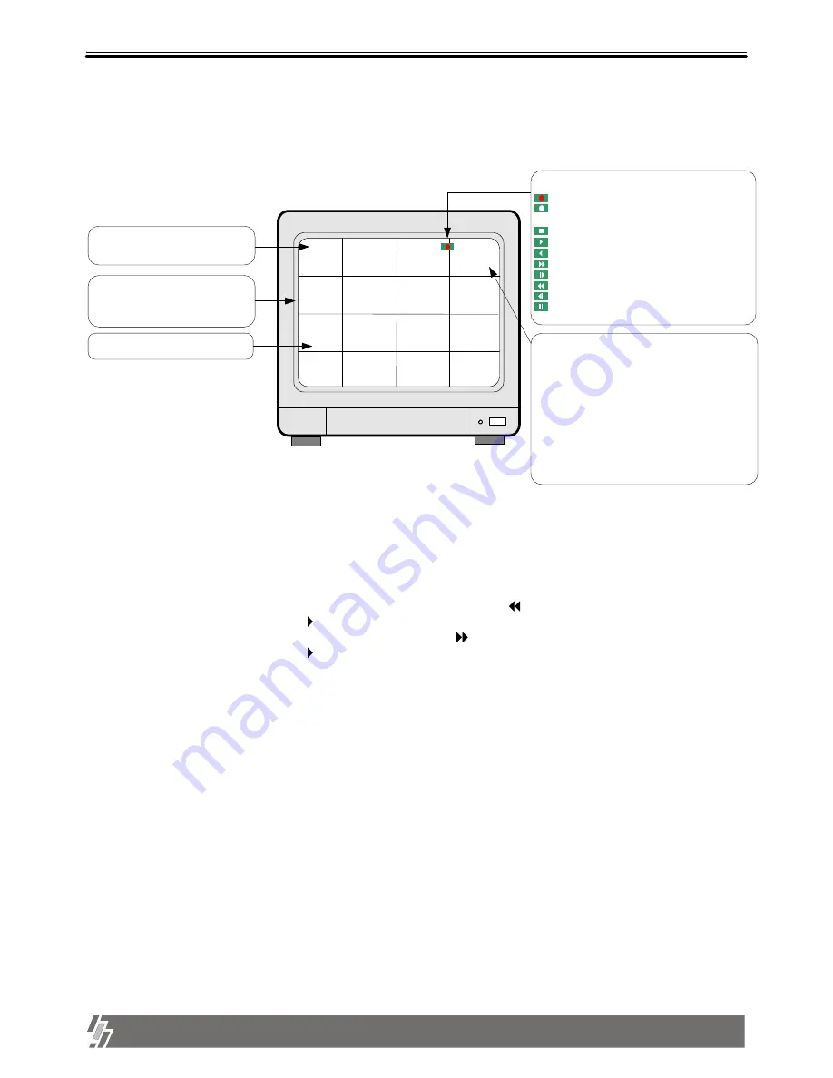
3-1. Basic display

1. Display of camera channel (camera title)

  In 16-split screen, camera title is shown in numbers by the system from 1 to 16, and in 4-split and 

 9-split screen, camera title set by user is shown.

2. Shows how much space in HDD is recorded

  a. R(RECORD) indicates percentage of HDD space used until now.

 b. P(PLAY) indicates starting point from which next playback will start. It is the point where last

   playback stopped.  To start playback from the first of recording, press (   ) button to set P(PLAY) at 0.00%, 
   and then press [Playback] button (   ).

  To replay reverse direction from the end of recording, press (    ) button to move to the end of recording,
  and then press [Playback] button (   ).

2002  /  APR  /  01      PM  01: 00: 00

1

Basic display

R    10.56%
P      9.34%

2

3

4

5

6

7

8

9

10

11

12

13

14

15

16

Turn on the power switch, and  system shows live display from ch 1 to 16 as following figure.
 system already started to record picture data automatically.

Chapter 3 .  Operation

TIM

1. indicate current status of 
      Recording
      Recording stand-by (No motion or alarm detected 
            in motion or alarm recording mode)
      Stop
      Playback in forward direction
      Playback in backward direction
      x times high speed playback in forward direction
      x times low speed playback in forward direction
      x times high speed playback in backward direction
      x times low speed playback in backward direction
      Pause ( Temporary stop of palyback)

3. Operation

5. Percentage of HDD space and  next playback point
- R : Percentage HDD space used
- P : End of last playback
        (Next playback starts from this point) 

Status of HDD detected
???.?? : Unknown HDD detected
- - - . - -: No HDD detected

- TIM : TIMER RECORDING
- MOT : MOTION RECORDING
- ALM : ALARM RECORDING

4. Indicates channel of camera

2. Current year/month/day/time
    In playback mode, it represents time
    of recording

3. Split screen
    Full screen by ch, 4-split, 9-split or
    16-split screen are available

Summary of Contents for 15-VP16-CDRW

Page 1: ...15 VP16 HDD2 15 VP16 CDRW VER 2 42 16 Channel Digital Video PROCESSOR Safety Security ...

Page 2: ...wer connection 9 Chapter 3 Operation 3 1 Basic Display 10 3 2 Playback 14 3 3 SYSTEM Log in 16 3 4 Set up 17 Chap 4 Specification and Configuration 4 1 SPECIFICATIONS 25 4 2 Configuration 15 VP16 HDD2 26 15 VP16 HDD2 15 VP16 CDRW ALL ABOUT IMAGE RECOGNITION PROCESSING 3 1 1 MODE 11 3 1 2 FRZ 11 3 1 3 SEQ 11 3 1 4 ZOOM 12 3 1 5 PIP 12 3 1 6 P T 13 3 4 1 Basic operation 17 3 4 2 CAMERA SETUP 18 3 4 ...

Page 3: ...t side of the unit 7 Put the unit at well ventilated place and do not put heat generating objects on the unit When it is installed inside 19 inch mounting rack together with other devices please check built in ventilation fan of the rack is properly running Before installing Video Processor be sure to thoroughly review and follow the instructions in this User s Manual Pay particular attention to t...

Page 4: ...a of pictures from camera on hard disk drive after converting it into digital data Describe how to install and operate this unit 4 DC power adapter and power cable Convert AC 110V or AC 220V into DC 12V to supply to unit 3 Remote controller IR remote controller enables to operate unit apart from the unit 2 User manual for 16 ch 15 VP16 HDD2 15 VP16 CDRW The most stable and reliable real stand alon...

Page 5: ...el 1 2 Name and function of each button 19 CD RW or Mobile Rack Back up Recording device 13 1 9 5 15 11 7 14 10 2 6 16 12 3 4 8 Enter Menu Setup Play Record Overwrite MODE ZOOM SEQ P T FRZ PIP 13 Record Records picture data on hard disk drive 14 Stop Stops recording or playback 17 Fast backward High speed playback in reverse direction in playback mode or moving to the start of recorded data when i...

Page 6: ...better quality of display 6 ALARM RELAY Connect to alarm input and relay output 9 ETHERNET Connect to Ethernet port for TCP IP option 8 TERATRAY CONNECTION Connect to HDD BAY for extension of HDD space 10 D C 12V Port for DC 12V 5A C o m m P o r t Rear Panel 1 2 Name and function of each button 11 POWER SWITCH WITH LED DC Power Switch With LED Generally speaking cutting power to system may cause t...

Page 7: ...O LENS VIDEO DC AC24V DC12 V P DC LEVEL Rear view of CAMERA VIDEO A IN OUT VIDEO C IN OUT VIDEO B IN OUT Chapter 2 Installation Procedure Notice This system accepts camera with both PAL system or NTSC system and the set at PAL or NTSC system automatically Connect camera and monitor while DC power switch on the front panel is off 2 Installation CH16 CH1 MONITOR 1 CH16 CH1 MONITOR 2 LOOP S VHS VIDEO...

Page 8: ... is cut RS 485 Connected to P T Controller or Speed Dome Camera RJ 45 Connected to LAN WAN or Internet When TeraTray is connected to unit supply power to TeraTray first and then to unit TERATRAY CONNECTION DC 12V ETHERNET C o m m P o r t ALARM RELAY RS 485 r k s PTZ CAMERA PC 2 3 Monitor S VHS connection Connect S VIDEO monitor to MONITOR OUT S VHS on the rear panel of unit VIDEO A IN OUT S Video ...

Page 9: ...tallation 13 lower Upper 1 14 Alarm Alarm Sensor Speed Dome RS 485 All GNDs are connected to each other on circuit 1 10 9 8 7 6 5 4 3 2 11 25 24 23 22 21 20 19 18 17 16 15 14 13 12 D1 D2 D3 D4 GND GND D5 D6 D7 D8 GND GND D9 D10 D11 D12 GND GND D13 D14 D15 D16 NO COM NC RELAY Output 1 2 3 4 5 6 7 8 0 9 1 1 1 1 1 1 1 1 1 2 1 3 4 5 6 7 9 20 2 2 2 2 3 2 4 1 2 2 5 6 G N D G N D GROUP1 GROUP 2 G N D G N...

Page 10: ...The jumper setting of HDD must be on Master as specified by HDD manufacturer The jumper setting must be done properly as specified by HDD anufacturer Fix HDD on the bottom of case using screws included in the package And jumper setting of CD RW DRIVE must be on Slave Mobile Rack must be on master the other HDD on Slave Selection of video system NTSC PAL The set the video system of camera NTSC or P...

Page 11: ...ower switch and system shows live display from ch 1 to 16 as following figure system already started to record picture data automatically Chapter 3 Operation TIM 1 indicate current status of Recording Recording stand by No motion or alarm detected in motion or alarm recording mode Stop Playback in forward direction Playback in backward direction x times high speed playback in forward direction x t...

Page 12: ... press number of channel you want to freeze Picture of channel you selected is freezed and icon is displayed on the left of camera title Press FRZ button again to exit F 3 SEQ SEQUENCE If press SEQ button in live display when it is in full screen of any channel it shows full screen pictures in rotation Rotation time interval can be set in SYSTEM SETUP MISCELLANEOUS SETUP TIMER SETUP R 10 56 P 9 34...

Page 13: ...g make it move faster Display of ZOOM R 10 56 P 9 34 L R CH 01 T B 5 PIP PICTURE IN PICTURE While you see picture of specific channel in full screen you can see small size pictures of remaining channels in rotation if you press PIP button Time interval of PIP small size picture can be set in SYSTEM SETUP MISCELLANEOUS TIMER SETUP If press SEQ button while it is in PIP mode picture in full screen a...

Page 14: ...oller a Basic control button ENTER Transmit COMMAND while pressed UP DOWN Selection of menu item LEFT RIGHT Select Command For details refer to SYSTEM SETUP MISCELLANEOUS PAN TILT CMD SETUP If you press this button long times consecutively it changes to screen position adjustment mode In case position of 16 split screen is not in the center of display unit you can adjust screen position using UP D...

Page 15: ...time and by event in GOTO MENU 2002 APR 01 PM 01 00 00 1 R 10 56 P 5 37 2 3 4 5 6 7 8 9 10 11 12 13 14 15 16 1 3 Search When system is in stop mode press Playback button for a couple of seconds and you can enter into GOTO MENU 2002 APR 01 PM 01 00 00 1 Basic display of GOTO menu R 10 56 P 5 37 2 3 4 5 6 7 8 9 10 11 12 13 14 15 16 GOTO MENU PERCENT TIME DATE EVENT LIST PERCENT GOTO Start End 2002 0...

Page 16: ...splayed by pressing Fast forward button or Fast backward button 4 Speed of playback 2002 APR 01 PM 01 00 00 1 Display of Playback R 10 56 P 5 37 2 3 4 5 6 7 8 9 10 11 12 13 14 15 16 1 1X 64X 32X 16X 8X 2X 1X 1 2X 1 4X 1 4X 1 2X 1X 2X 4X 8X 16X 32X 64X 5 ZOOM 6 PAUSE 7 Others a system memorizes status of last playback For instance you searched recorded data in backward playback and stopped at the p...

Page 17: ... into SYSTEM SETUP If it is not system goes back to live display mode LOGIN SYSTEM ENTER PASSWORD _ _ _ _ _ _ _ _ _ INPUT YOUR OWN PASSWORD THEN PRESS ENTER TO EXIT PRESS MENU Enter password Default P W 1 Display of Login Notice To protect hard drive from damaged turn off DC power switch of unit after you first press MENU button If you press MENU button unit stops recording and HDD head is not in ...

Page 18: ...Notice We recommend users to clear all data on HDD and set at FACTORY DEFAULT in the very first operation of this unit In case you added HDD replaced HDD or replaced EPROM Program for unit also clear data on HDD and set at FACTORY DEFAULT again Display of SETUP SYSTEM SETUP CAMERA SETUP TIME DATE SETUP RECORD SETUP HDD MANAGEMENT MISCELLANEOUS SETUP TCP IP SETUP FACTORY DEFAULT SELECT UP DOWN ENTE...

Page 19: ...t b Enter letters Alphabet numbers and symbols using Left and Right buttons c Move to next camera for settings using Up and Down buttons d If you have same word repeated in camera title for each channel move to the word you want to copy and press Record button for copy and move to the location to put it and press Playback to paste CAMERA COLOR SETUP CH NUMBER BRIGHTNESS CONTRAST SATURATION HUE GAI...

Page 20: ... detection area by block X x Y Using direction keys select the first location of cell and press ENTER button and then select the second location of cell using direction keys and again press ENTER button You will see color of all cells inside 2 coordinates is changed to green motion detection area ALL OFF ON All cells are set as a detection area or no detection area When it is in ALL OFF press ENTE...

Page 21: ...ode in Time Lapse VCR e REFRESH RATE In Motion or Alarm recording mode system records pictures at a certain time interval REFRESH RATE even though there is no motion detected or alarm activated 20 SEC Records pictures from all channels at time interval of 20 sec regardless of motion detected or alarm activated f DURATION Records for DURATION time when a motion is detected or an alarm is activated ...

Page 22: ...e 02 03 COPY REC PASTE PLAY SELECT EDIT NUMERIC SYSTEM SETUP CAMERA SETUP TIME DATE SETUP RECORD SETUP HDD MANAGEMENT MISCELLANEOUS SETUP TCP IP SETUP FACTORY DEFAULT HDD CLEAR HDD INFORMATION CD R BACKUP b Show information of HDDs installed inside unit or HDD Bay SELECT PRESS ENTER c You can backup the recorder data by using CD R media 1 Search the data what you want to back up and check the star...

Page 23: ... to item you want to change using Up and Down buttons change type using Left and Right button To set altogether as a whole locate cursor at ALL and select type you want using Left and Right button Just exit and all setting is memorized by the system 8 MISCELLANEOUS SETUP SYSTEM SETUP CAMERA SETUP TIME DATE SETUP RECORD SETUP HDD MANAGEMENT MISCELLANEOUS SETUP TCP IP SETUP FACTORY DEFAULT BUZZER SE...

Page 24: ...ENTER SYSTEM SETUP CAMERA SETUP TIME DATE SETUP RECORD SETUP HDD MANAGEMENT MISCELLANEOUS SETUP TCP IP SETUP FACTORY DEFAULT BUZZER SETUP ALARM SETUP TIMER SETUP PAN TILT CMD SETUP BAUDRATE SETUP PASSWORD SETUP 1 SEC 3 SEC 2 SEC Set time interval for SEQ PIP Picture in picture FULL SCREEN Time interval of pictures rotating in channel sequence when SEQ button is pressed QUAD 9 SPLIT Time interval o...

Page 25: ...MERA TITLE MOTION MASK PAN TILT COMMAND SYSTEM STATUS SYSTEM SETUP CAMERA SETUP TIME DATE SETUP RECORD SETUP HDD MANAGEMENT MISCELLANEOUS SETUP TCP IP SETUP FACTORY DEFAULT NO NO NO NO NO RUN You can set all groups of settings as a whole or set them group by group Move to menu items using Up and Down buttons and select YES or NO and then move to RUN Press ENTER button to set at FACTORY DEFAULT for...

Page 26: ... LIVE PLAYBACK YES YES FULL 720 H X480 V ACTIVE PIXELS 16 SCREEN 180 H X120 V ACTIVE PIXELS MAX 30 FRAME SEC E IDE HDD JPEG REAL TIME TIME LAPSE EVENT MOTION SEARCH STILL ALARM SINGLE FULL QUAD 9 SPLIT 16 SPLIT 15 VP16 HDD2 15 VP16 CDRW CD R TCP IP 16 ALARM INPUT 1 RELAY OUTPUT PAN TILT ZOOM AND FOCUS VIDEO MONITORING RECORDING PLAYBACK OTHER MODEL NO OPERATION TEMPERATURE OPERATION HUMIDITY IR RE...

Page 27: ...26 ALL ABOUT IMAGE RECOGNITION PROCESSING 15 VP16 HDD2 15 VP16 CDRW 4 Configuration 2 Configuration of Video Processor ...

Reviews: