S260-20-9
7
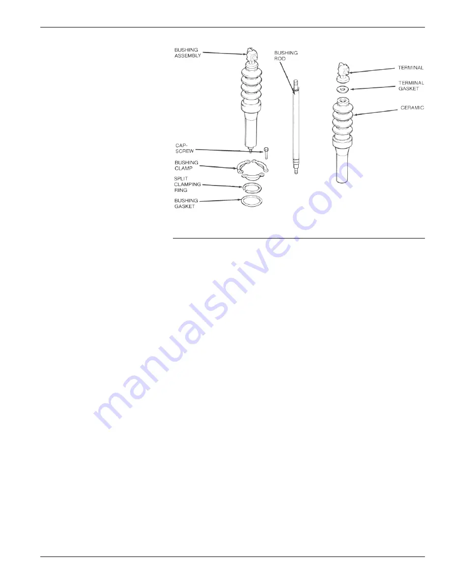
Figure 14.
Bushing parts.
TEST 2: Proceed as follows:
1. Close the switch.
2. Ground switch tank and head.
3. Ground the outer two bushings
(Phase A and Phase C).
4. Apply test voltage (37.5 kv) to the
center bushing (Phase B).
• The switch should withstand the
test voltage for 60 seconds.
TEST 3: Proceed as follows:
1. Open the switch.
2. Ground switch tank and head.
3. Connect and ground all three bush-
ings on one side of the switch.
4. Connect together the three bush-
ings on the other side of the switch.
5. Apply test voltage (37.5 kv) to the
ungrounded side of the switch.
• The switch should withstand the
test voltage for 60 seconds.
6. Reverse the test and ground con-
nections to the bushings.
7. Again apply test voltage (37.5 kv) to
the ungrounded bushings.
• The switch should withstand the
test voltage for 60 seconds.
TEST RESULTS: These high potential
withstand tests provide information on
the dielectric condition of the switch.
A. If the switch passes the closed con-
tacts tests (Test 1 and 2) but fails
the open contacts test (Test 3) the
cause is likely to be in one or more
of the main contact assemblies.
B. If the switch fails the closed con-
tacts tests (Test 1 and 2) the cause
is likely to be a diminished electri-
cal clearance or failed insulation.
C. After correcting the problem, retest
to confirm the repair.
SHOP REPAIR PROCEDURES
The procedures described in this sec-
tion should be performed under the
cleanest possible conditions. No spe-
cial tools are required for any of the
repair procedures.
Bushings
Bushing replacement generally con-
sists of a thorough cleaning and care-
ful examination for chips, cracks, or
other mechanical damage during the
periodic maintenance inspection.
Bushings must be replaced whenever
damage is discovered.
Note that the contact structures are
suppor ted from the bottom of the
bushings. If more than one bushing is
damaged, replace only one bushing at
a time to maintain contact alignment.
To replace a bushing refer to Figure
14 and proceed as follows:
1. With the switch untanked, remove
the nut, lockwasher and flatwash-
er holding the contact structure to
the lower end of the bushing rod.
2. Remove the three hex head cap-
screws and clamps that secure the
bushing to the head and lift out the
complete bushing assembly.
3. Remove and discard the lower bush-
ing gasket.
4. The complete bushing assembly can
be replaced or new porcelain only
can be installed depending upon the
extent of damage. If new porcelain
only is to be installed, proceed as
follows:
A. Unscrew the bushing terminal
and withdraw the rod from the
bottom of the porcelain; discard
the terminal gasket.
B. Insert the rod assembly all the
way into the new porcelain, mak-
ing sure the roll pin is seated in
the locking groove in the top of
the bushing.
C. Assemble the ter minal to the
bushing rod using a new terminal
gasket; tighten to a torque of 35
ft-lbs.
NOTE: Apply a very small amount of
petroleum jelly to the knurled surface
of the inside face of the terminal
before assembling the terminal to the
bushing rod.
5. Twist off the split aluminum clamping
ring from the old bushing and reuse
if it is in good condition; replace the
ring if damaged.
NOTE: The clamping ring cushions and
distributes the pressure between the
porcelain and the clamps. DO NOT OMIT.
6. Install the bushing assembly (new or
reworked) into the head casting
using a new lower bushing gasket.
Position the bushing with the stud-
end of the terminal pointing out-
ward.
7. Position the clamping ring with the
split centered between two clamp-
ing bolts.
8. Reassemble the bushing to the head
casting. Tighten the clamping bolts
evenly, a little at a time, to a torque
of 6-10 ft-lbs.
NOTE: Clamping forces must be applied
gradually and equally in rotation to each
bolt. This results in an evenly distributed
gasket sealing pressure.
9. Reconnect the bushing to the con-
tact structure.
10. Recheck contact alignment as spec-
ified on page 9 or 12.
Contacts
The Type VR switch utilizes two sets of
wedge-shaped moving contacts; one set
for arcing, the second set for load-carry-
ing (Figure 3). The Type VCR switch uti-
lizes a set of wedge-shaped contacts for
arcing, a set of bayonet-type contacts
for load carrying, and resistors in series
with the arcing contacts for damping
capacitor switching transients (Figure
2). Contact service and alignment pro-
cedures are similar for both switches.


