


Quik-drive Tap-Changers
The present load tap-changer product offering consists of
three Quik-Drive tap-changers (see Figures 18—20). Each
device is sized for a specific range of current and voltage
applications and share many similarities in their construc-
tion. The primary benefits of Quik-Drive tap-changers
are: direct motor drive for simplicity and reliability; high-
speed tap selection for quicker serviceability; and proven
mechanical life (one million operations). Quik-Drive load
tap-changers meet IEEE
®
and IEC standards for mechani-
cal, electrical, and thermal performance.
Common Quik-drive Tap-Changer
Features
•
Neutral Light Switch – A switch is triggered to close by
the Reversing Switch Assembly or the Main Contact
Assembly to indicate to the Control that the tap-changer
is in the Neutral position.
• Position Indicator Drive – A common indexing mecha-
nism is shared between the tap-changers for driving
the Position Indicator.
•
Safety Switches – In addition to the limit switches in the
Position Indicator, microswitches are employed on the
tap-changers to interrupt power to the motor so that
they cannot be powered beyond the 16 Raise or 16
Lower positions. These Safety Switches are triggered by
a cam that is driven from the Main Contact Assembly.
•
Logic Switches (Back-Off Switches) – The Logic
Switches are used in parallel with the Safety Switches,
based on the polarity of the Reversing Switch, to
ensure proper operation of the tap-changer.
Quik-drive Tap-Changer Mechanism
A tap change is initiated by the Control. After some rota-
tion of the drive gear connected to the motor, a holding
switch energizes the motor through a separate circuit until
the indexing motion is completed. The indexing occurs
very quickly. The total elapsed time to complete the action
is approximately 250 milliseconds from the time the index-
ing signal is started by the control. Each full turn of the
Geneva drive gear rotates the main Geneva/contact drive
assembly one tap position, which is 20 degrees.
Reversing Switch
The reversing switch function changes the polarity of the
tapped winding. When a Quik-Drive tap-changer is in the
neutral position, the reversing switch is open.
The reversing switch motion on the Quik-Drive tap-changer
occurs as the main movable contacts enter or leave the
neutral position. The Main Contact Assembly engages the
Reversing Switch either directly or through a linkage when
the main switch is in the neutral position. The first tap step
in either direction rotates the Reversing Switch Assembly
to engage the appropriate contacts.
Additionally, the Main Contact Assembly, or its drive, and
the Reversing Switch Arm provide a mechanical stop
located 320° on either side of the neutral position so that
the tap-changers cannot be moved past 16 Lower or 16
Raise.
Quik-drive Motors drive Systems
Either AC Synchronous Motors or Induction Motors are
used on Quik-Drive tap-changers. The motor uses a
Holding Switch Circuit that is activated after the Control
signals for a tap change. The Holding Switch is engaged
throughout the duration that the movable contacts are in
motion to ensure that the tap change cycle is complete.
Because of differences in rotational speed and braking
characteristics, the AC Synchronous Motor uses a cam of
different timing duration than the Induction Motor to acti-
vate the holding switch. The cam on the AC Synchronous
Motor is engaged for 270° of rotation while the induction
motor cam is engaged for 105° of rotation.
The AC Synchronous Motor utilizes a phase-shifting net-
work, consisting of a capacitor and a resistor, to operate
properly when powered by a single-phase source. This
motor has a permanent magnet rotor that arrests the
inertia of the system once power to the motor is removed;
therefore, no braking mechanism is required. The AC
Synchronous Motor uses a 12 µF capacitor for 60 Hz
applications and a 15 µF capacitor for 50 Hz applications.
Induction Motors use a phase-shifting capacitor and
require a friction-type brake to stop the motor between
tap changes. Brakes use various means to interrupt the
braking action while the movable contacts are in motion
so that full motor torque is dedicated to completing the tap
change. Induction Motors use a 50 µF capacitor for 50 and
60 Hz operation.
VR-32 Voltage Regulator Installation, Operation, and Maintenance Instructions
20
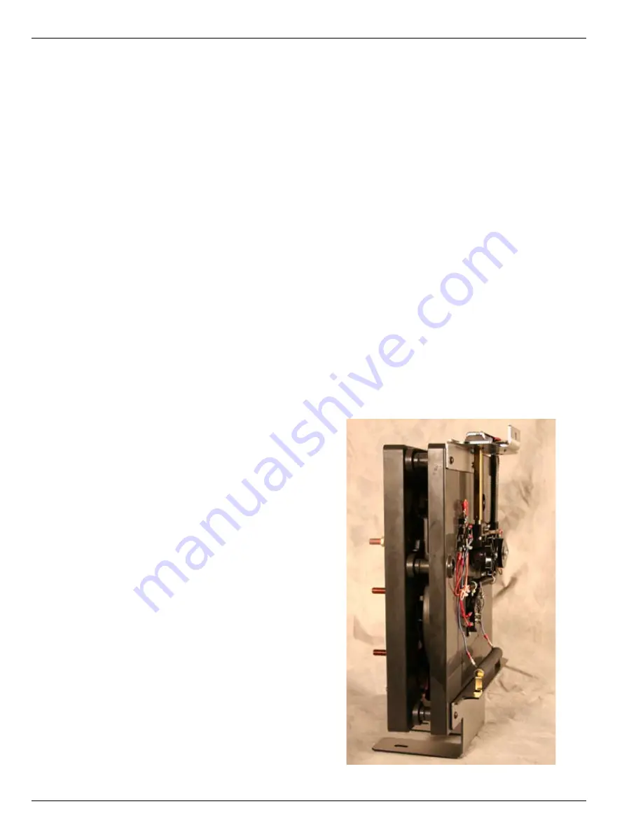
Figure 18 .
QD-3 Quik-Drive tap-changer .


