background image

4

2

CHILLED FLUID VOLUME REQUIREMENT

The volume of water in a piping system loop is critical to the smooth and proper operation of a chilled water system. If
sufficient volume of water is not there in the system, the temperature control can be lost resulting in erratic system
operation and excessive compressor cycling. Therefore, to prevent this effect of a ‘Short Water Loop’ ensure that total
volume of water in the piping system loop equals or exceeds 3 Gallons per Nominal Ton of cooling capacity for standard
air conditioning applications and 6 Gallons per Nominal Ton of cooling capacity for process cooling jobs where accuracy
is vital and applications requiring operation at very low ambient temperatures and low loading conditions.

For example, chiller model ASQ100B operating with a design water flow rate of 205 GPM for a standard air conditioning
application would require 100 (Nom. Cap.) x 3 = 300 Gallons of water in the piping system loop.

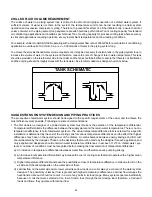
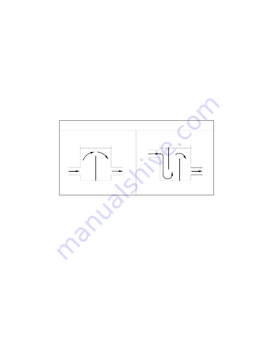
To achieve the aforementioned water volume requirements, it may be necessary to install a tank in the piping system loop to
increase the volume of water in the system and therefore, reduce the rate of change of return water temperature. This tank
should be provided on the return water side to the chiller and the tank should be baffled to ensure that there is no stratification
and the entering stream thoroughly mixes with the tank water. See recommended tank design schematics below:

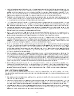
SUGGESTIONS ON SYSTEM DESIGN AND PIPING PRACTICES

The prospective chilled water system should be designed to the specific requirements of the owner and to achieve the
most efficient system possible. Following are some recommendations:

The first decision a designer of a chilled water system must make is the selection of the temperature differential.
Temperature differential is the difference between the supply water and the return water temperatures. There is no one
temperature difference for all chilled water systems. The actual temperature difference that is selected for a specific
installation is determined by the cost of the cooling coils for various temperature differences and the effect that higher
differences may have on the operating cost of the chillers. A careful balance between energy savings and first cost
should be made by the designer. These are the decisions that must be made by the designer for each application and
only experienced designers should entertain water temperature differences in excess of 12

0

F on chilled water sys-

tems. A number of conditions must be recognized before making the final selection of temperature differential:

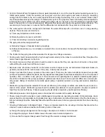
a) An increase in temperature differential decreases water flow and therefore saves pumping energy.

b) An increase in temperature differential may increase the cost of cooling coils that must operate with a higher mean

temperature difference.

c) Higher temperature differentials increase the possibilities of loss of temperature difference in coils due to dirt on the

air side and chemical deposits on the water side of them.

d) Laminar flow on the water side due to lower velocities at low loads on a coil is always a concern of the water system

designer. The possibility of laminar flow is greater with higher temperature differences. Laminar flow reduces the
heat-transfer rate and should not occur in a coil at any point in its load range. Many systems operate inefficiently
because of coils that were selected at too low a friction loss through them at design load; therefore, at reduced
loads and flows, they operate with laminar flow.

TANK SCHEMATIC

Summary of Contents for ASQ Series

Page 1: ......

Page 2: ......

Page 3: ...pecifications options 5 8 Physical data 9 12 Selection procedure 13 14 Performance data 15 20 Electrical data 21 Water side pressure drop 22 Unit dimensions 23 28 Typical schematic wiring diagram 29 3...

Page 4: ...BREAKER OPTIONS 11 COOLER OPTIONS A STANDARD WITH VICTAULIC CONN B FLANGE CONN OPTIONAL C ASME STAMPED WITH VICTAULIC CONN OPTIONAL D ASME STAMPED WITH FLANGE CONN OPTIONAL A STANDARD B COMPRESSOR CIR...

Page 5: ...minate short circuiting of airflow All fans are die cast aluminum propeller type with aerodynamic design top discharge provided with protective grille mounted on top panel within the unit casing All c...

Page 6: ...prove the thermal efficiency End plates support sheets are 14 gauge galvanized steel formed to provide structural strength Each coil is pressure tested in the factory at not less than 450 psi air pres...

Page 7: ...e indicating the type of alarm the corresponding compressor the related chiller and which location The microprocessor consists of the following hardware 1 User Interface Board Provided with simple to...

Page 8: ...er cooler during the off cycle UNDER VOLTAGE AND PHASE PROTECTION Protects against low incoming voltage as well as single phasing phase reversal and phase imbalance by de energizing the control circui...

Page 9: ...860 860 860 860 860 COOLER COOLER PART NUMBER 800 660 91 800 660 91 800 660 91 800 660 91 800 660 91 800 660 92 800 659 05 800 659 05 800 660 52 SHELL DIAMETER mm 273 273 273 273 273 273 324 324 324...

Page 10: ...ER 800 660 52 800 660 55 800 660 55 800 660 59 800 660 59 800 660 59 800 660 62 800 660 62 800 660 52 2 SHELL DIAMETER mm 324 406 406 406 406 406 406 406 324 LENGTH mm 2697 2744 2744 2737 2737 2737 27...

Page 11: ...660 55 2 800 660 59 2 800 660 59 2 800 660 59 2 SHELL DIAMETER mm 324 324 324 406 406 406 406 406 406 LENGTH mm 2697 2697 2697 2744 2744 2744 2737 2737 2737 TOTAL WATER HOLDING VOLUME Liters 227 227 2...

Page 12: ...OOLER COOLER PART NUMBER 800 660 59 2 800 660 59 2 800 660 59 2 800 660 62 2 800 660 62 2 800 660 68 2 800 660 68 2 SHELL DIAMETER mm 406 406 406 406 406 457 457 LENGTH mm 2737 2737 2737 2737 2737 279...

Page 13: ...98 0 97 0 96 0 95 TABLE 2 EVAPORATOR FOULING FACTOR HR FT2 0 F BTU 0 00010 0 00025 0 00050 0 00075 0 00100 CAPACITY CORRECTION FACTOR 1 000 0 992 0 978 0 965 0 951 POWER INPUT FACTOR 1 000 0 997 0 990...

Page 14: ...99 0 98 0 97 0 96 0 95 Referring to pressure drop chart page 22 pressure drop at 15 7 LPS 36 kPa for selected model NOTE The total flow rate should be divided by 2 for models ASQ220B ASQ440B to find...

Page 15: ...55 1 61 0 10 1 132 2 51 4 67 5 8 6 123 3 47 4 74 8 7 2 113 8 43 2 82 8 6 0 103 7 41 0 87 1 5 4 98 5 ASQ 070B 63 6 70 3 10 1 152 6 59 9 78 5 8 6 143 7 55 9 87 5 7 2 134 2 51 8 97 3 6 1 124 2 49 6 102 5...

Page 16: ...60B 60 3 63 3 10 7 144 6 56 0 69 9 9 1 134 4 51 5 77 1 7 6 123 7 46 8 85 0 6 3 112 4 44 4 89 3 5 7 106 6 ASQ 070B 70 4 72 8 10 8 168 9 66 0 81 1 9 2 158 4 61 5 90 2 7 7 147 5 56 7 100 2 6 4 136 1 54 2...

Page 17: ...SQ 060B 63 9 65 0 11 0 153 3 59 5 71 6 9 4 142 7 54 8 78 9 7 9 131 5 49 9 87 0 6 6 119 8 47 4 91 3 6 0 113 7 ASQ 070B 74 6 74 4 11 2 179 1 70 1 82 8 9 5 168 1 65 3 92 2 8 0 156 7 60 3 102 4 6 7 144 8...

Page 18: ...060B 188 3 60 3 2 9 7 5 177 2 66 1 2 5 7 1 162 7 73 9 2 1 6 5 147 1 82 6 1 7 5 9 138 9 87 3 1 5 5 5 ASQ 070B 217 1 69 6 2 9 8 7 205 8 76 9 2 5 8 2 191 4 86 5 2 1 7 6 176 1 97 0 1 7 7 0 168 0 102 7 1 6...

Page 19: ...060B 208 1 62 9 3 1 8 3 195 1 68 7 2 7 7 8 178 6 76 4 2 2 7 1 161 1 85 0 1 8 6 4 152 0 89 7 1 6 6 1 ASQ 070B 242 5 72 3 3 1 9 7 229 2 79 7 2 7 9 1 212 4 89 5 2 2 8 5 194 8 100 2 1 8 7 8 185 7 106 0 1...

Page 20: ...B 225 6 65 2 3 2 9 0 211 6 71 1 2 8 8 4 193 8 78 9 2 3 7 7 175 2 87 6 1 9 7 0 165 5 92 3 1 7 6 6 ASQ 070B 263 7 74 5 3 3 10 5 249 2 82 1 2 9 9 9 231 0 92 1 2 4 9 2 212 0 103 2 2 0 8 5 202 2 109 2 1 8...

Page 21: ...119 2 612 3 95 8 16 3 00 21 60 48 8 230 1200 5 22 PW 578 716 1 137 8 665 3 110 2 3 119 2 612 3 95 6 16 3 00 21 60 48 8 230 1200 5 22 PW 596 734 2 137 8 665 3 110 4 2 119 2 612 3 95 4 16 3 00 21 60 48...

Page 22: ...If an application requires certain water flow rate outside these limits please check with your nearest dealer sales office CURVE No Maximum GPM MODEL No ASQ220B ASQ230B ASQ240B ASQ250B ASQ260B ASQ270B...

Page 23: ...SIONS ASQ045B ASQ050B ASQ055B ASQ060B ASQ070B NOTE ALL DIMENSIONS ARE IN MILLIMETERS UNLESS OTHERWISE SPECIFIED ASQ080B ASQ090B ASQ100B MODEL A B C ASQ080B 1500 330 389 ASQ090B ASQ100B 1730 360 414 DI...

Page 24: ...24 ASQ115B ASQ130B ASQ140B ASQ150B DIMENSIONS NOTE ALL DIMENSIONS ARE IN MILLIMETERS UNLESS OTHERWISE SPECIFIED...

Page 25: ...25 DIMENSIONS NOTE ALL DIMENSIONS ARE IN MILLIMETERS UNLESS OTHERWISE SPECIFIED ASQ160B ASQ170B ASQ180B ASQ190B ASQ200B...

Page 26: ...DIMENSIONS ASQ220B ASQ230B ASQ240B ASQ250B ASQ260B ASQ270B ASQ280B NOTE ALL DIMENSIONS ARE IN MILLIMETERS UNLESS OTHERWISE SPECIFIED MODEL A B ASQ220B ASQ250B 2250 422 ASQ260B ASQ280B 2200 483 DIMENSI...

Page 27: ...27 DIMENSIONS ASQ300B ASQ320B ASQ330B ASQ340B NOTE ALL DIMENSIONS ARE IN MILLIMETERS UNLESS OTHERWISE SPECIFIED...

Page 28: ...MENSIONS ASQ350B ASQ360B ASQ380B ASQ400B ASQ420B ASQ440B NOTE ALL DIMENSIONS ARE IN MILLIMETERS UNLESS OTHERWISE SPECIFIED MODEL A B C ASQ350B ASQ400B 2200 3420 483 ASQ420B ASQ440B 2130 3490 510 DIMEN...

Page 29: ...CB20 L1L FMC8 L3L L2L 37F L2K FMC6 L3K L1K COMP1 OILHTR COMP2 OILHTR EX7 EX8 ALCO COMP1 CONTACTOR EEVB JUMPER DIP SWITCH HOT GAS BYPASS SOLENOID LIQUID LINE SOLENOID1 LIQUID LINE SOLENOID2 POWER DECR...

Page 30: ......

Page 31: ...NECTION WITH CB OPTIONAL LPS CONNECTION WITH OUT CB OPTIONAL 1 1 LPS1 LPS2 63A 63B REMOVE JP2 REMOVE JP3 CONTROL PANEL FAN2 FAN1 CONTROL PANEL T2 70A B 71A B COMP TI L3 L1 L2 1A 1 2 A1 A2 UVR 1 UVM JU...

Page 32: ...f Compressor 1 rises the corresponding fans are energize accordingly to the fan stage ON set point If the discharge pressure falls below the fan stage OFF set point value the corresponding fans will t...

Page 33: ...250 C or 1200 ohm at 500 C 4 Digital input reading incorrectly a Check if the auxiliary 220 Vac voltage is present in the electrical box b Check if the AC input on the Board is correctly connected to...

Page 34: ...power supply voltage is into the specified limits 24VAC 10 d Check the fuse F1 replace with 1AT 250V if blown 10 Digital Outputs not responding a Check Digital Output cables integrity no short circuit...

Page 35: ...n and untreated water may result in scale and deposit formation causing reduced cooler efficiency or heat transfer and corrosion or pitting leading to possible equipment damage The more scale forming...

Page 36: ...equipment at different temperature drops It should be noted that temperature drop outside the aforesaid range is not permitted as it is beyond the optimum range of control and could adversely affect t...

Page 37: ...cycle units On and Off based on the cooling demand Parallel arrangements permit adding chillers in the future for plant expansion with the appropriate considerations beforehand In the series arrangeme...

Page 38: ...ed the quantity of water flowing through the load gradually decreases from design flow to no flow The three way mixing valve has the same effect on the load as the two way valve as the load reduces th...

Page 39: ...an indicator of demand the sequencing of chillers is dependent on water flow The chillers are rated in gallons per minute the actual flow to the system determines the number of chillers that should b...

Page 40: ...into the supply header This flow indicates a need for additional chiller capacity and another chiller pump starts Excess bypass flow with reference to the set points in the system controller in the o...

Page 41: ...s The roof must be reinforced for supporting the individual point loads at the mounting isolator locations It must be checked and ensured that the concrete base is perfectly horizontal and levelled es...

Page 42: ...air vent connections should be provided at all low and high points in the piping system to permit complete drainage of the cooler and piping as well as to vent any air in the pipes Hand shut off valve...

Page 43: ...st decision a designer of a chilled water system must make is the selection of the temperature differential Temperature differential is the difference between the supply water and the return water tem...

Page 44: ...e provided to so that water volume changes can be accommodated Expansion tanks are generally connected to the suction side of the pump lowest pressure point Pumps in parallel must always operate at th...

Page 45: ...ar when rigging to prevent the slings from damaging the unit CAUTION All panels should be in place when rigging Care must be taken to avoid damage to the coils during handling Insert packing material...

Page 46: ...in mm 2 If unit is installed in special pit please observe the same tolerance for walls Pit height should not exceed the unit height FIGURE 1 STRAIGHT WALL MODEL NUMBER A B ASQ045B ASQ070B 2500 2000...

Page 47: ...DELS ASQ220B ASQ280B MODELS ASQ300B ASQ440B MODELS ASQ045B ASQ070B MODEL A ASQ140B 1586 ASQ150B 1586 ASQ160B 2094 ASQ170B 2094 ASQ180B 2094 ASQ190B 2094 ASQ200B 2094 NOTE All dimensions are in mm MODE...

Page 48: ...1023 1006 1000 994 871 836 819 813 808 ASQ250B 1075 1040 1023 1017 1012 887 852 835 829 824 ASQ260B 1114 1080 1063 1057 1051 966 931 914 908 903 ASQ270B 1119 1084 1067 1062 1056 968 934 916 911 905 AS...

Page 49: ...1069 945 911 893 888 882 ASQ250B 1172 1137 1120 1114 1109 984 949 932 926 921 ASQ260B 1211 1177 1160 1154 1148 1063 1028 1011 1005 1000 ASQ270B 1216 1181 1164 1159 1153 1065 1031 1013 1008 1002 ASQ280...

Page 50: ......

Reviews: