4
0
•
The unit’s longitudinal axis should be parallel to the prevailing wind direction in order to ensure a balanced air flow
through the condenser coils. Consideration should also be given to the possibility of down-drafts caused by adjacent
buildings, which may cause recirculation or uneven unit airflow. For locations where significant cross winds are ex-
pected, an enclosure of solid or louver type is recommended to prevent wind turbulence interfering with the unit airflow.
When units are installed in an enclosure, the enclosure height should not exceed the height of the unit.
•
The location should be selected for minimum sun exposure and away from hot air sources, steam, exhaust vents and
sources of airborne chemicals that could attack the condenser coils and steel parts of the unit. Avoid locations where
the sound output and air discharge from the units may be objectionable.
•
If the location is an area which is accessible to unauthorized persons, steps must be taken to prevent access to the unit
by means of a protective fence. This will help to prevent the possibility of vandalism, accidental damage or possible
harm caused by unauthorized removal of panels or protective guards exposing rotating or high voltage components.
•
The clearance requirements prescribed above are necessary to maintain good airflow and provide access for unit
operation and maintenance. However, it is also necessary to consider access requirements based on practical consid-
erations for servicing, cleaning and replacing large components.
•
The unit must be installed on a ONE-PIECE, FLAT and LEVELLED {within 1/2'' (13 mm) over its length and width} /
CONCRETE BASE that extends fully to support the unit. The carrying or supporting structure should be capable of
handling complete operating weight of the unit as given in the Physical Data tables in this Catalog.
•
For ground level installations, it must be ensured that the concrete base is stable and does not settle or dislocate upon
installation of the unit which can strain the refrigerant lines resulting in leaks and may also cause compressor oil return
problems. It is recommended that the concrete slab is provided with appropriate footings. The slab should not be
connected to the main building foundation to avoid noise and vibration transmission.
•
For rooftop installations, choose a place with adequate structural strength to safely support the entire operating weight
of the unit. The unit shall be mounted on a concrete slab similar to ground installations. The roof must be reinforced for
supporting the individual point loads at the mounting isolator locations. It must be checked and ensured that the
concrete base is perfectly horizontal and levelled, especially if the roof has been pitched to aid in water removal. It
should be determined prior to installation if any special treatment is required to assure a levelled installation else it
could lead to the above mentioned problems.
•
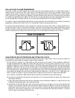
Vibration isolators are necessary for installing these chillers in order to minimize the transmission of vibrations. The
two types of vibration isolators generally utilized for mounting these units are Neoprene Pads and Spring Isolators.
Neoprene Pads are recommended for ground level normal installations jobs where vibration isolation is not critical and
job costs must be kept to a minimum. Spring Isolators are recommended for ground level installations which are noise-
sensitive areas or exposed to wind loads and all roof top installations. For critical installations (extremely noise and
vibration sensitive areas), follow the recommendations of structural and acoustical consultants.
•
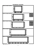
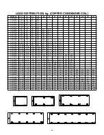
Based on the specific project requirements, choose the type of vibration isolators best suited for the application. Care-
fully select the vibration isolators’ models / configuration based on the respective point loads and place each mount in
its correct position following the Load Distribution Data and Mounting Drawings provided in this Catalog. Refer to the
Schematic Mounting Layout drawings provided in the IOM manual of these chillers for further details in this regard.
COOLER PIPING CONNECTIONS
The following pertinent guidelines are served to ensure satisfactory operation of the units. Failure to follow these recom-
mendations may cause improper operation and loss of performance, damage to the unit and difficulty in servicing and
maintenance:
•
Water piping must be connected correctly to the unit i.e., water must enter from the inlet connection on the cooler and
leave from the outlet connection.
•
A flow switch must be installed in the field piping at the outlet of the cooler (in horizontal piping) and wired back to the unit
control panel using shielded cable. There should be a straight run of piping of at least five pipe diameters on either side
of the flow switch. Paddle type flow switches can be obtained from COOLINE which are supplied as optional items.
•
The chilled water pump(s) installed in the piping system should discharge directly into the unit cooler. The pump(s)
may be controlled external to the unit - but an interlock must be wired to the unit control panel (as shown in the wiring
diagram) so that the unit can start only upon proof of pump operation.


