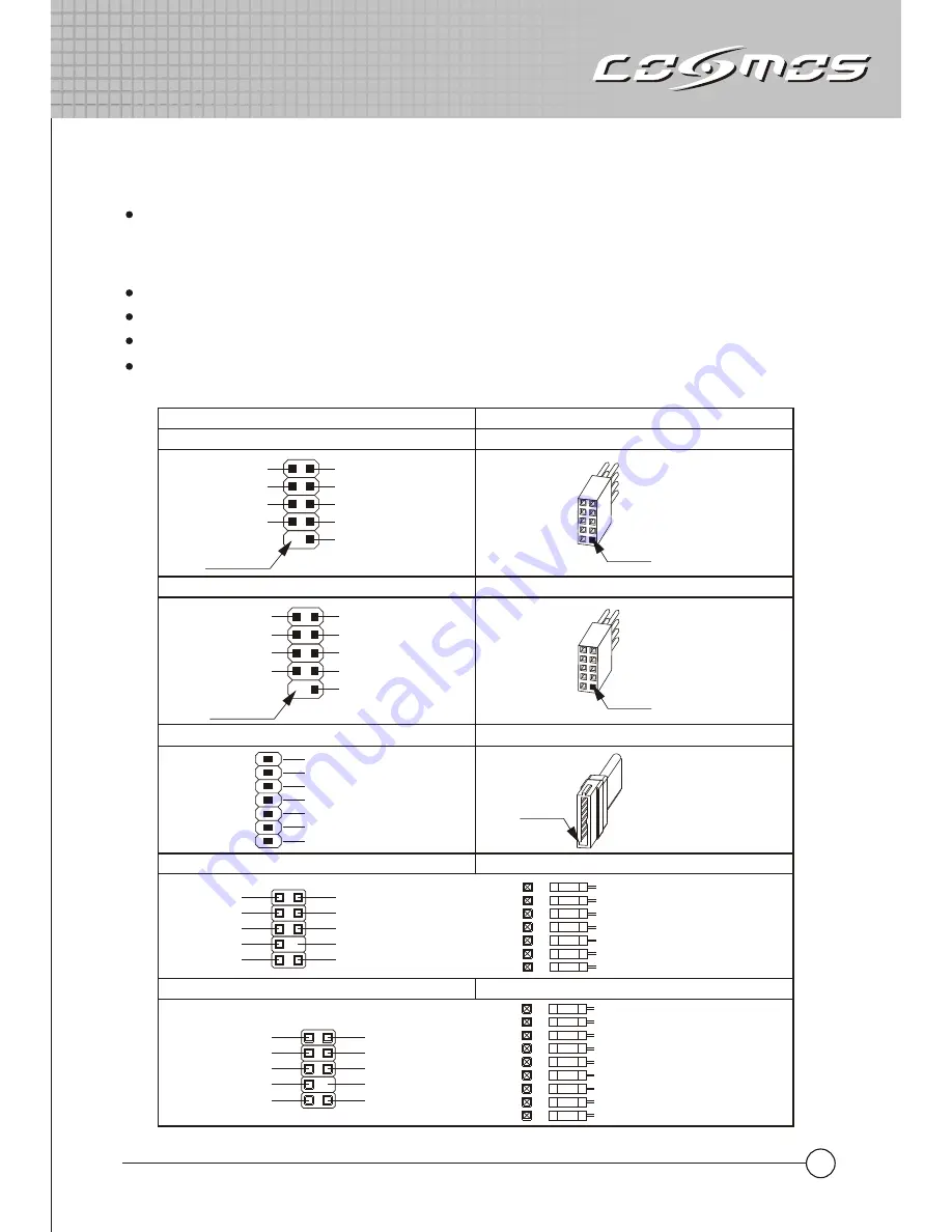
3. I/O Function Panel Installation Guide
Please refer to the illustration in the section of USB2.0, IEEE 1394a, eSATA and Audio connector
from the motherboard user manual. Please select the motherboard which uses the same USB2.0,
IEEE1394, eSATA, AC’97,HD Audio standard as below; otherwise, it will cause damages to
device(s).
The following illustration is a connection diagram for the front panel I/O cable.
NEVER connect an IEEE1394 cable to the USB2.0 connector. Doing so will damage the device.
NEVER connect a USB2.0 cable to the IEEE1394 connector. Doing so will damage the device.
On some motherboards, the connectors for IEEE1394, eSATA, USB2.0 and Audio are not the same
as the drawing below. Please check with your motherboard manual before installing.
MIC
MIC~BIAS
FPOUT-R
+5V
FPOUT-L
GND
AUD GND
RET~R
NO PIN
RET-L
Yellow-MIC
Red-MIC~BIAS
Black-AUD GND
Green-RET~R
Green/Green-FPOUT~R
Blue-RET~L
Blue/Blue-FPOUT~L
Azalia (Intel High Definition Audio)
HD Connector
AUD GND
PRESENCE#
SENSE1_RETURN
NO PIN
SENSE2_RETURN
PORT1L
PORT1R
PORT2R
SENSE_SEND
PORT2L
Yellow-PORT1L
Red-PORT1R
Brown-SENSE1_RETURN
Black-AUD GND
White-PRESENCE#
Orange-SENSE_SEND
Gray-SENSE2_RETURN
Green-PORT2R
Blue-PORT2R
AC'97
AC'97 Connector
Front panel IEEE 1394 connector
TPA+
GND
TPB+
+12V
USB+5V
LP-
LP+
GND
TPA-
GND
TPB-
+12V
GND
No Pin
IEEE 1394 connector
Motherboard
Cable
Front panel USB connector
USB connector
No Pin
USB+5V
LP-
LP+
GND
NC
Pin
Pin
11
Front panel eSATA connector
eSATA connector
Pin
GND
TXP
TXN
GND
RXN
RXP
GND


