


Technical Training
6
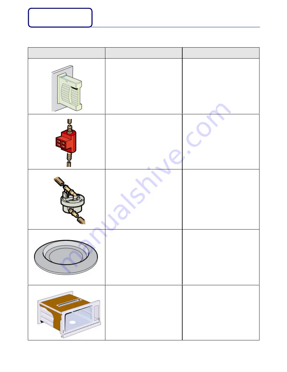
The different components
Designation
Function
Characteristics
Tank
The tank must
•
Be filled up to maximum level with
water before every cooking session.
•
Be emptied after every cooking
session
If the tap water is very hard, use
bottled water.
Never use demineralised water.
1 liter of water
The noise that can be heard if you
shake the tank when is empty comes
from the water level detector.
Pump
A triac (
TC1
) switches on the pump
The pump transfers the water from the
tank to the generator.
- 220/240V~
- 16W
When you reassemble the pump,
ensure there is no air bubble in the
circuit, and start the circuit up before
reassembling the panels
Flow meter
The flow meter is incorporated into the
water circuit, between the outlet of the
water reserve and the pump.
The water displacement makes a blade
turn on wich there is a magnet that
releases a transistor function (effect of the
field).
The impulses are counted by the
microprocessor which controls the
quantity of water going into the appliance.
•
Supply :
12V= between
+
and mass
symbol.
•
Out going voltage :
between # and
mass symbol.
Ø
5V= when it is not working
Ø
1,7V= when it is working
When you reassemble the flow meter
squeeze the pipes hermetically on it
with the Rilsan ring, and ensure there
is no air bubble in the circuit, and start
the circuit up before reassembling the
panels
Generator
A relay (
REL1
) switches on the generator.
The generator produces the heat to
change the water in steam.
The appliance is protected from
overheating by a safety thermostat KX1
(
200°C
) fitted under the generator.
- 220/240V~
- 1600W
- 33
Ω
Heating cover
A relay (
REL2
) switches on the heating
cover.
Throughout the whole cooking time, the
heating cover which is glued to the
external walls of the cavity keep the
temperature slightly higher 100°C to
prevent condensation. Its consists of two
elements in series of a total wattage of
390w
- 220/240V~
- 390W
- 133
Ω
(88
Ω
and 45
Ω
)
DIFFERENT
COMPONENTS
Summary of Contents for SOE100A
Page 1: ...SOE100X SOE100A Electronic Steam Oven ...
Page 12: ...Technical Training 11 OPERATING INSTRUCTIONS ...
Page 13: ...Technical Training 12 OPERATING INSTRUCITONS ...
Page 14: ...Technical Training 13 OPERATING INSTRUCTIONS ...
Page 15: ...Technical Training 14 OPERATING INSTRUCTIONS ...
Page 16: ...Technical Training 15 OPERATING INSTRUCTIONS ...


