Converters.TV 718 Operation Manual Download Page 3

Operating 
Controls

Transmitter 
Front Panel

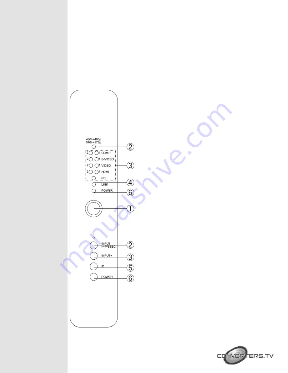
The following sections describe the hardware components of the unit with 
installation guide and setting methods.

① 

IR sensor


480i 

→ 

480p / 576i 

→ 

576p LED indicator and 

INPUT   -I

  

P/5SEC   button:  

Press   this   button   to 

select the  input  source   from   COMP1  to   PC  or 
press for 5 seconds to switch between interlace 
and progressive format, yellow LED light will turn 
on when switched from interlace to progressive 
format,   when   switching   from   progressive   to 
interlace the light will not turn on.


Input source selection:

 Press the input button 

to switch to your desired input sources from PC 
to COMP1, green LED will illuminate according 
to your selection.


Link LED:

 When the system is in search mode 

the blue LED will flash repeatedly, and when it is 
in signal linking mode it will slowly flash. When 
the LED is on and there is no flashing it means 
the system is ready and audio or video can be 
sent.


ID:  

Press   this   button   with   the   receivers   “ID” 

button for two seconds to connect the systems. 
Before   they   left   the   factory   the   systems   were 
already connected so there is no need for the 
user to reset the connection unless the systems 
cannot link up properly. Press the ID button for 
more   than   ten   seconds   to   switch   between 
Broadcast and Unicast mode. When the green 
LED is on it means the system is in Unicast mode 
and   when   the   Red   LED   is   lit   the   system   is   in 
Broadcast   mode.   The   default   mode   for   this 
system is Unicast and it is recommended to use 
this   for   home   use.   It   is   not   necessary   to   press 
both the transmitter and receiver buttons at the 
same time. 

Note:  

Due   to   the   nature   of   Broadcast   mode, 

which   has   no   uplink,   there   can   be   no 
communication   between   Transmitter   and 
Receiver, the result is the following:
• HDCP protected content should not be 
transmitted.
• CEC and EDID repeater functions cannot be 

supported.

Summary of Contents for 718

Page 1: ...Wireless Multi Format input Transmitter to HDMI Receiver Box ID 718 Operation Manual ...

Page 2: ...uding 480i p 576i p 720p 1080i VGA 60 72Hz SVGA 56 60 72Hz XGA 60 70Hz and 1080p 24 30fps Supports analog digital video audio input and HDMI output to display HDCP keysets allows each HDMI input to independently connect to an HDMI display Supports 3D comb filter and 3D noise reduction DNR Supports 3D noise reduction DNR Supports analog format conversion from 480i 576i to 480p 576p with a hot key o...

Page 3: ...sh When the LED is on and there is no flashing it means the system is ready and audio or video can be sent ID Press this button with the receivers ID button for two seconds to connect the systems Before they left the factory the systems were already connected so there is no need for the user to reset the connection unless the systems cannot link up properly Press the ID button for more than ten se...

Page 4: ...ox with S Video and RCA cables The SVideo1 Video1 Audio1 and SVideo2 Video2 Audio2 are two individual loops for source equipments PC in AUDIO These slots are for connecting the PC and or audio output port of your source equipment such as Notebook or PC with D Sub15pin and R L cables HDMI inputs 1 2 These slots are for connecting the HDMI or DVI output ports of your source equipments such as DVD pl...

Page 5: ...with Transmitters ID button for two seconds to connect the systems Before they left the factory the systems were already set up so there is no need for the user to reset the connection unless the systems cannot link up properly Press the ID button for more than ten seconds to switch between Broadcast and Unicast mode When the green LED is on it means the system is in Unicast mode and when the Red ...

Page 6: ...Rear Panel HDMI output This slot is to connect the HDMI cable to the HDMI input of your display Power Plug in the 5V DC power supply included in the package and connect the adaptor to an AC outlet ...

Page 7: ...witch between Interlace and Progressive format Power Press this button to turn on standby the unit HDMI 1 2 Press no 1 or 2 buttons to select HDMI 1 or 2 inputs Component 1 2 Press no 1 or 2 buttons to select Component 1 or 2 inputs S Video1 2 Press no 1 or 2 buttons to select S Video 1 or 2 inputs Video1 2 Press no 1 or 2 buttons to select Video 1 or 2 inputs Connection and Installation Unicast M...

Page 8: ...Broadcast Mode Remote Control distance ...

Page 9: ...20x576 50Hz 576i 720x576 50Hz 720p 1280x720 50 60Hz 1080i 1920x1080 50 60Hz 1080p 1920x1080 24 30fps Output Signal Specifications PC Resolution Vert Rate VGA 640x480 60 72Hz SVGA 800x600 56 60 72Hz XGA 1024x768 60 70Hz HDTV Resolutions Vert Rate 480p 720x480 60Hz 480i 720x480 60Hz 576p 720x576 50Hz 576i 720x576 50Hz 720p 1280x720 50 60Hz 1080i 1920x1080 50 60Hz 1080p 1920x1080 24 30fps ...

Page 10: ...ng 256 bit AES based encryption Application Bandwidth Control Channel allows two way communications of 10Kbps Input ports 2 x Components with R L 2 x Video and 2 x S Video with R L 2 x HDMI 1 x PC with R L 1 x IR Blaster Output port 1 x HDMI Power Supply Transmitter 5V 6A DC US EU standards CE FCC UL certified Receiver 5V 2 6A DC US EU standards CE FCC UL certified ESD Protection Human body model ...

Reviews: