background image

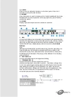
Baud Rate: 115200bps

Data bit: 8 bits
Parity: None
Flow Control: None
Stop Bit: 1

RS-232 & Telnet
Commands

Command

Description

Paramenter

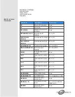
P0 

Power Off (Standby) 

None 

P1 

Power On 

None 

IPCONFIG 

Display The Current IP 
Configure

None 

SIPADDR X.X.X.X 

Set Ethernet IP 
Address 

X=0~255 

SNETMASK 
X.X.X.X 

Set Ethernet Net Mask  X=0~255 

SGATEWAY 
X.X.X.X 

Set Ethernet Gateway  X=0~255 

HTTPPORT N1 

Set Http Port Number  N1=10~65535 

TELNETPORT N1 

Set Telnet Port 
Number 

N1=10~65535 

RSTIP 

IP Configuration Set To 
<DHCP>

None 

A N1 

Select input N to output 
A

N1=1~4 

B N1 

Select input N to output 

B

N1=1~4 

C N1 

Select input N to output 

C

N1=1~4 

D N1 

Select input N to output 

D

N1=1~4 

I N1 

Select input N to all 
output

N1=1~4 

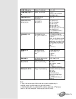
EDIDMODE 

Show EDID Mode 

None 

EDIDMODE N1 

Set EDID Mode 

N1=0 (Appoint), 1(All) 

EDIDALL 

Show EDID Mode 
Source for All

None 

EDIDALL N1 

Set EDID Mode Source 
for All

N1=0~9* (ref. OLED 
EDID ALL) 

EDIDIN 

Show EDID Mode 
Source for All

None 

Summary of Contents for 15365

Page 1: ...4 x 4 HDMI UHD over CAT5e 6 7 Matrix with Control System ID 15365 Operation Manual ...

Page 2: ... 25 30 4096x2160 50 60_YUV420 Supports individual EDID or common EDID Supports pass through of audio formats LPCM 2 5 1 7 1CH Dolby Digital 2 5 1CH DTS 2 5 1CH Dolby Digital Plus Dolby TrueHD Dolby Atmos and DTS HD Master Audio HDCP 1 4 for 4 HDMI inputs and 4 HDBaseT outputs with HDBaseT 5PlayTM features Input port HDCP support Standard and Apple mode The Apple mode selection to guarantees the us...

Page 3: ... control signal from the package include remote control only 3 OUT A D Press OUT button once a time along with an IN buttons to select an input source for an output display i e OUT A IN1 TAKE or OUT B IN4 TAKE 4 IN 1 4 Press IN button to select input from 4 sources 5 TAKE Press this button to confirm the selection of an IN and an OUT button If this button is not pressed the selection will not exec...

Page 4: ...tion on Command Settings Note Although both IR Extender and IR Learner may look the same they are however different IR Extender is designed with more reddish color whereas IR Learner has a brownish color and a red dot on the back to be distinguished in between Please pay extra attention in connecting and using them 2 EXT OUT 1 8 Connect with IR Blaster for IR signal transmitting 3 TRIGGER IN 1 8 C...

Page 5: ...Connect to HDBaseT Receivers and output to TV display or HD Amplifier for image output and or audio display IR INs are to connect with IR Receivers for IR signal reception from the designated input HDMI ports 9 SERVICE This slot is reserved for firmware update use only 10 CONTROL Connect from PC Laptop with active internet service or Ethernet switch Hub for WebGUI control and or data transmitting ...

Page 6: ... OUT button If this button is not pressed the selection will not execute 6 CANCEL Press this button to cancel the selection 7 PRESET Press this button the OLED will show preset selections then select from IN 1 4 and press TAKE to confirm the selection or press CANCEL to cancel the selection 8 LOCK Press to lock on all button functions on the front panel Press again to relieve the lock function 9 M...

Page 7: ... with similar outlook a part no CBL IR10C3SA200A sticker has been placed to differentiate the difference on IR Learner RS 232 Protocols Matrix Control Device Pin Assignment Pin Assignment 1 NC 1 NC 2 TX 2 RX 3 RX 3 TX 4 NC 4 NC 5 GND 5 GND 6 NC 6 NC 7 NC 7 NC 8 NC 8 NC 9 NC 9 NC ...

Page 8: ... 255 HTTPPORT N1 Set Http Port Number N1 10 65535 TELNETPORT N1 Set Telnet Port Number N1 10 65535 RSTIP IP Configuration Set To DHCP None A N1 Select input N to output A N1 1 4 B N1 Select input N to output B N1 1 4 C N1 Select input N to output C N1 1 4 D N1 Select input N to output D N1 1 4 I N1 Select input N to all output N1 1 4 EDIDMODE Show EDID Mode None EDIDMODE N1 Set EDID Mode N1 0 Appo...

Page 9: ...None SOURCEDET N1 Show Input N1 Signal N1 1 4 SINKINFO Show All Output Information None SINKINFO N1 Show Output N1 Information N1 A D INNAME Show all Input name None INNAME N1 Show Input N1 name N1 1 4 INNAME N1 N2 Set Input N1 Name N1 1 4 N2 ABCDEFGH Max Length 8 OUTNAME Show all Output name None OUTNAME N1 Show Output N1 name N1 A D OUTNAME N1 N2 Set Output N1 name N1 A D N2 ABCDEFGH Max Length ...

Page 10: ... A D to_source output port 1 4 to_mcu IR OUT 1 to_notice IR All 1 n A D 1 4 ex IR_SELECT TO_ZONEA SHOW IR_SELECT ShowAll Show IR port Status IR_SELECT a n add b n c n Show Current Setting a to_zone output port A D to_source input port 1 4 to_mcu IR OUT 1 to_notice IR All 1 b c from_zone input port A D from_source input port 1 4 from_mcu IR OUT 1 from_notice IR All 1 n A D 1 4 ex IR_SELECT TO_ZONEA...

Page 11: ...ut A D c MemProtection OperMode d On Off MemProtection HdmiPassThrough EthernetFallBack LPPF1 LPPF2 LongReach HDBaseT Auto OperMode VALENS FwUpd a b Update Valens Firmware of Specified Chip a Local Remote HDBaseT TX RX b HDBaseT output A D FADEFAULT Update Valens Firmware of Specified Chip ETH_FADEFAULT All Ethernet Configure Set to Factory Default CYP Set Ethernet MAC address 48 Bit c nn nn nn nn...

Page 12: ...g r or x0D in the end to allow the system to recognize it as an end of the command IREMIT n n1 n2 n3 Send IR Code to Designated Output Port n IR Zone Source bn1 Port Zone no 1 4 A D n2 0 n3 IR Code IRLEARN N IR Signal Learning and Save into Data N IR code string RELAY N N1 Relay Switch Setting N 1 8 N1 Open Close Toggle ex RELAY 1 Close TRIGGER N N1 N2 Trigger Switch Setting N Status Info Active M...

Page 13: ...m _mcu to_notice from_zone from_source from_notice from _mcu 1 Though from_source is not allowed an actual hardware design has build in a route to transfer the IR signal that is not to be controlled through command or software 2 Though from_zone is not allowed and actual hardware design has build in a route to transfer the IR signal according to Matrix setting that is not to be controlled through ...

Page 14: ...e chips Auto Automatic detection and connection making between local and remote and chips LongReach Long reach mode between local and remote chips HdmiPassThrough HDMI pass through mode between local and remote chips EthernetFallBack Fallback to normal Ethernet connection instead of HDBaseT LPPF1 Low Power Profile mode 1 between local and remote chips LPPF2 Low Power Profile mode 1 between local a...

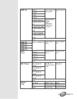
Page 15: ...AC3 4 K2K Exit EDID IN1 Same as EDID All Select Input 1 4 EDID Same as EDID All EDID IN2 EDID IN3 EDID IN4 Matrix Preset Preset 1 IN OUT default No 1 4 A 1 B 2 C 3 D 4 Preset 2 Preset 3 Preset 4 Exit HDCP Input IN1 Standard Apple Set IN1 4 in Standard Apple mode Standard IN2 Standard Apple IN3 Standard Apple IN4 Standard Apple Exit Network Setup IP Mode DHCP Static Static IP Setup Static IP 192 16...

Page 16: ...t signal HDCP IN2 On Off IN3 On Off Detect IN3 IN4 source with without signal HDCP IN4 On Off Exit Sink A Info HPD On Off Detect Sink A display with without Hot Plugging R sense Type Manuf Native Video Format Audio Format RSEN On Off Exit Sink B Info Same as Sink A Info Detect Sink B display with without Hot Plugging R sense Same as Sink A Info Sink C Info Detect Sink C display with without Hot Pl...

Page 17: ... port and the PC Laptop are connected to the active networks To access the Telnet control in Windows 7 click on the Start menu and type cmd in the Search field then press Enter Under Windows XP go to the Start menu and click on Run type cmd with then press Enter Under Mac OS X go to Go Applications Utilities Terminal See below for reference Once in the command line interface CLI type telnet then t...

Page 18: ...ntrol Type HELP to list the available commands Note All the commands will be not executed unless followed by a carriage return Commands are case insensitive If the IP is changed then the IP Address required for Telnet access will also change accordingly ...

Page 19: ... of the devices connected to the Control System will show up Then user may use the IP Address to find the control device through Telnet WebGUI or even RS 232 Hyper Terminal tools WebGUI Control On a PC Laptop that is connected to an active network system open a web browser and type device s IP address available from OLED monitor on the web address entry bar A security page will appear to ask for U...

Page 20: ...ork and System Settings Configuration pages for users to control Routing Settings Click on Routing Settings to select an input for output and the selection will turn orange naming inputs outputs preset and restore video preset HDBaseT Info Click on HDBaseT Info to read current CAT5e 6 output ports status ...

Page 21: ...select EDID Mode and Set EDID Input content Macro Settings Macro 1 8 works align with Trigger IN 1 8 which means when a trigger signal is activated the control system will execute the command under Macro Setting Click on Macro Settings to execute Macro action Click on the pen icon mark to edit the command settings up to 8 Macro sets and to set its parameter and delay time of command up to 16 per e...

Page 22: ...ed within the same Telnet system Internet area RS 232 COM ports IR and Relay devices connected through the Relay outputs of Control System with delay time It is suggested the delay time is 100ms once the setting is confirmed double click on Save Changes Command set to control the devices within the same telnet system ...

Page 23: ...ontrol the Relay devices require to set the Port number Click on Save Change to confirm the setting Command under 128 characters including space can be build up to 128 commands command over 128 characters and under 512 characters including space can be build up to 32 command in addition with 96 commands of 128 characters under Click on Save Change to save the command inserted ...

Page 24: ...tring will show in the bottom column Click on Save Changes to store the command For IR command saving insert the command on the bottom column and click on Save changes to store the command Trigger Settings Click on Trigger Settings to view the current trigger status and edit the trigger behavior Default setting Status is on Low Active is on Enable and Mode is on Change where Status represent curre...

Page 25: ... of the selection range can be set under RS 232 or Telnet Network Settings Click on Network Settings to set the device s IP Mode Once the change is saved the system will reset the IP address on the device automatically and user will need to re enter the IP address to continue the WebGUI function System Settings ...

Page 26: ...st press the take button to execute the selection Download Current Configuration is to save the current setting into your PC Laptop and Restore Configuration is to bring up a saved setting from your PC Laptop Reset to Default and Reboot the Unit is to set the device back to factory setting and restart the device again Connection Diagram ...

Page 27: ......

Page 28: ...K 50 60 YUV420 VGA WUXGA RB HDMI Cable Length 10M 1080p 5M 4K2K CAT Cable Length 100M 1080p 70M 4K2K IR Frequency 30 50kHz Baud Rate Up to 115200 bps Power Supply 24V 2 7A DC US EU standards CE FCC UL certified ESD Protection Human Body model 8kV air gap discharge 4kV contact discharge Weight 3450g Chassis Material Metal Silkscreen Color Black Dimensions 482mm W 274mm D 49mm H Operating Temperatur...

Page 29: ... 60 1280 960 60 1280 1024 60 1360 768 60 1366 768 60 1400 1050 60RB 60 1440 900 60RB 60 1600 900 60 1600 1200 60 1680 1050 60RB 60 1920 1080 60 1920 1200 60RB 1440 576i 50 1440 480i 60 720 480p 60 720 576p 50 1280 720p 50 60 1920 1080i 50 60 1920 1080p 24 25 30 50 60 3840 2160p 24 25 30 3840 2160p 50 60 YUV420 4096 2160p 24 25 30 4096 2160p 50 60 YUV420 ...

Reviews: