


33
Installing the device
1
Place the device in a location which ensures the following:
• Easy access to any externally-connected wires
• ZigBee mesh networking efficiency
Note:
Make sure the device has good ZigBee wireless
reception by (1) ensuring it is within range of another
ZigBee device and (2) avoiding other electrical
equipment that may cause interference with the ZigBee
signal (such as cordless telephones that operate on the
2.4 GHz frequency.)
• Avoiding unnecessary exposure to extreme environmental
conditions.
IMPORTANT!
Do not place the device in direct sunlight.
2
If an external thermistor is used with the device, place
it away from direct sunlight, drafts, doorways, skylights,
windows, and exterior walls for best accuracy.
3
Position the tray against the wall or other flat surface.
4
If you are using the internal contact, position the device so
that the narrow indentation that marks the internal contact
(on the long edge of the cover) aligns with the external
magnet (not included).
A
A
Indentation
5
Mark the locations of the four screw holes on the wall.
6
If mounting the device to drywall, remove the tray from the
wall and drill four 3/16-inch (4.75 mm) mounting holes at the
four screw hole locations (A) previously marked on the wall.
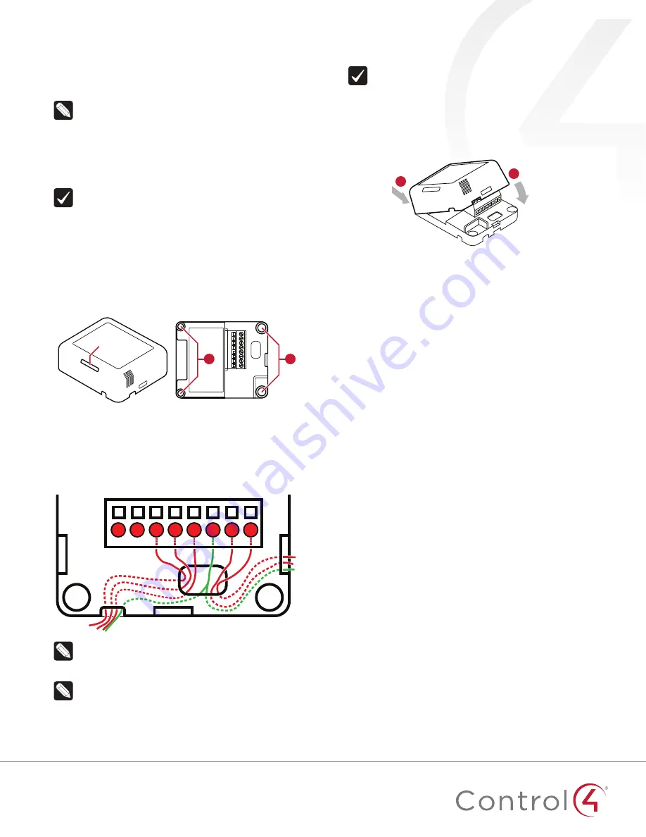
7
Thread any contact or thermistor wires from the wall through
the openings in the tray and to the terminal block.
T
C1
C2
Cm
C3
C4
VO Cm
Note:
The two
Cm
(common/ground) pins are
connected and can be used interchangeably.
8
Insert and tighten the mounting screws.
Note:
You may optionally choose to use robust two-
sided tape to mount the tray assembly to the wall or
other flat surface, as long as the tape won’t prevent the
back of the tray from sitting flush against the mounting
surface.
9
Connect the wires from the tray to the terminals in the cover,
matching the proper wires to the target terminal locations.
Important!
When using multiple external contact
sensors, or when using an external contact sensor along
with an external thermistor, you
must
connect each
device to one of the Common (Cm) pins in addition
to the appropriate sensor or thermistor pin to make
a proper wiring connection. See the “Sample wiring
configurations” section of this document for examples.
10
Attach the cover assembly to the tray:
A.
Align the cover edge’s
two latching tabs with
corresponding tab receivers
on the tray’s edge.
B.
Close the cover by rocking
it toward the other end of the
tray until it snaps into place
with the tray.
A
B
Configuring
To configure your device:
1
Add the device to your Composer Pro project. When
prompted to identify the device, press the
ID
button on the
face of the cover four times. The green LED blinks twice to
confirm the ID has been sent to the Control4 system.
- OR -
In Composer Express, add a device into the project, scan for
ZigBee devices, then press the ID button on the face of the
cover four times.
2
In the driver’s
Properties
tab, view or configure the settings
explained below under “Properties,” then click
Set
to the
right of the setting after each change.
3
Add generic contact drivers (such as
Door Contact Sensor
,
Gate
, and
Motion Sensor
) in
System Design
view, then
connect the generic driver to the appropriate connection on
the C4-Z2C device in
Connections
view.
4
For programming, use these events:
•
Missed Checkin:
Triggers when the device misses a
controller check in for the number of times specified in
the driver’s “Missed Checkin Limit” setting.
•
Online:
Triggers when the device comes online.
•
Offline:
Triggers when the device goes offline.
•
Reboot:
Triggers when the device reboots.
Properties
General properties
•
Log Level:
Standard for most drivers, this property
allows you to filter which message types display in the
Lua Output
window. Options 0 - 5 correspond to Fatal
through Trace levels, increasing in level of verbosity.
Options are 0=Fatal, 1=Error, 2=Warning, 3=Info, 4=Debug,
and 5=Trace. Default is
1 - Error
.


