


6
Step two: Place the Telephone Ring Detector Module and
Wireless Contact Sensor.
1
After connecting the Wireless Contact Sensor to the
ELK 930 Telephone Ring Detector Module, you can place the
module out of sight and mount the Wireless Contact Sensor
to a nearby wall or surface using the sensor’s enclosed molly
anchors.
2
After connecting the ELK-930 into the telephone line circuit
path and to the Wireless Contact Sensor, secure the module
to an appropriate and out-of-sight surface using the two
included adhesive pads.
3
Mount the Wireless Contact Sensor to a nearby wall or
surface using the Contact Sensor’s enclosed molly anchors.
Note:
Many times the junction box for the telephone line
circuit is large enough to conceal the Telephone Ring
Detector Module.
Programming in Composer Pro
Step one: Add the Wireless Contact Sensor driver to the
Composer project.
1
Open Composer Pro and the project, then select the
System
Design
view.
2
Under
Search
, enter
Control4 Wireless Contact Sensor
.
Figure 12: Wireless Contact Sensor driver search
3
Select the contact sensor to add it to the project.
Step two: Add lighting events to rooms.
1
In
System Design View
, add (if needed) the desired lighting
device to the event room.
2
Add a generic Contact Switch driver to the room where the
event will take place and rename it “Telephone Ring Sensor” .
3
In
Connections View
, bind the Telephone Ring Sensor driver’s
Contact Sensor input to the appropriate contact output of
the Contact Sensor.
Figure 13: Binding the Telephone Ring Sensor to the Contact Sensor
4
In the
Programming View
, from the
Device Events
window
in the upper left, select the
Telephone Ring Sensor
, and in
the
Telephone Ring Sensor Events
pane immediately below,
select
When the Telephone Ring Sensor closes
.
5
In the
Actions
pane in the upper right, select the lighting
device.
6
In the
Light Actions
pane, select
Toggle
, and drag the green
arrow icon into the
Script
pane two times.
7
In the
Actions
pane, select
Programming Control
. Then, in
the
Programming Control Actions
pane, enter a delay time
(for example, 500-1,500 milliseconds).
8
Drag the green arrow icon and drop it between the two
Toggle actions.
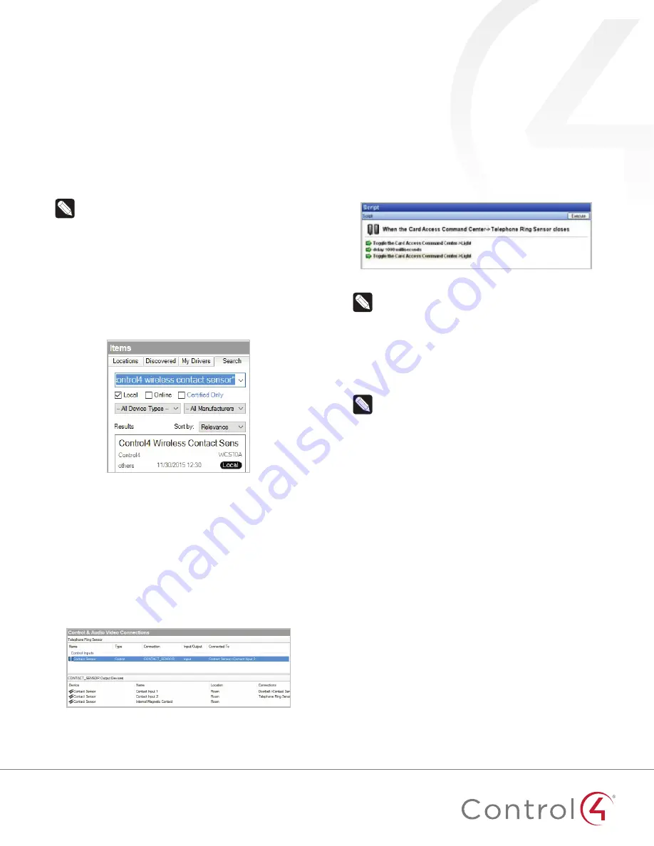
Figure 14: Programming
Note:
You can repeat the delay-and-toggle steps
multiple times as desired. If the instructions above are
used “as is,” the light will flash only once. The delay
time can be varied depending on the installer’s and the
homeowner’s preferences. If the homeowner doesn’t like
the abrupt flashes, the script can be modified to use a
series of ramp-to-level actions instead.
Step three: Add audio events to rooms.
Note:
Control4 does not include an Announcement
agent to support interrupting and resuming music
sessions, so a workaround has been devised to enable
this capability. To create audio events that interrupt and
resume an existing music session in a room, you need
to make use of unused audio out ports on other devices
in the project. An unused audio out port is any physical
audio out port not currently connected to some other
device in the project. Some commonly unused audio out
ports in projects are the RCA jacks in Speaker Points
and any unused audio out ports on home controllers.
1
In Composer, go to the
System Design View
and add a new
room called “Phantom Room” for every room where you plan
for the event to take place. (This room name will be used
throughout these instructions. During actual installation, you
should create your preferred room name such as “Phantom
Family Room” or “Phantom Garage.”)


