background image

 21

2.

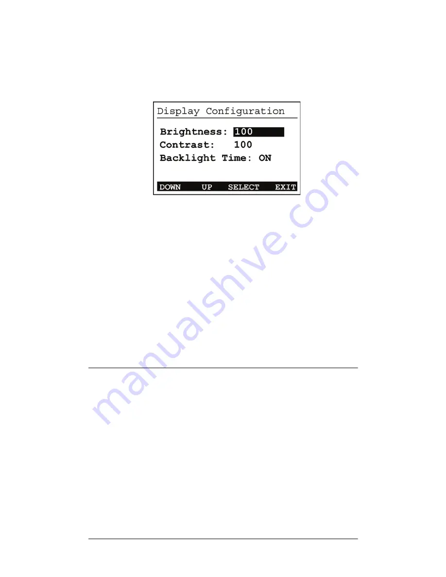
Use the buttons or the Select Dial to choose a setting 
to change: Once you press the Select button (or 
press the dial), you enter Edit mode.

3.

In Edit mode, use the buttons or Select Dial to 
change the highlighted setting. Press the 

OK

 button 

(or press the dial) to save the change and exit Edit 
mode.

Brightness:

 Supported range: 0 to 100 

Contrast:

 Supported range: 0 to 100 

Backlight Timeout:

 Supported settings are

Off (always off)

1 to 90 seconds (default is 10 seconds)

On (always on)

4.

Press the Exit


button to return to the In to Out 

Assignments screen.

Options Available in Composer

The following options are available in Composer:

Volume curve: 

The volume curve default 

follows the Control4 speaker-point volume 
curve. The volume curve can be changed to 
match the V1 curve using Composer.

5-band parametric equalizer:

 A 5-band 

parametric equalizer is available in 
Composer for tighter output control.

Summary of Contents for Multi Channel Amplifier- 16

Page 1: ......

Page 2: ...registered trademarks of their respective owners Copyright 2009Control4 All rights reserved Control4 the Control4 logo and Everyday Easy are registered trademarks or trademarks of Control4 Corporatio...

Page 3: ...iew 7 Chapter 2 Installing the Multi Channel Amplifier 9 Plan Your Physical Layout 10 Connect Audio Input Sources and Speakers 11 Connect to the Network and Power 12 Set Up Logical Connections 12 Set...

Page 4: ...iv FCC Interference Statement 23 Industry Canada Statement 23 Recycling Information 24 Warranty 24 Index 25...

Page 5: ...This indicates a potentially hazardous situation that if not avoided may result in death or serious injury DO NOT IGNORE A WARNING IMPORTANT This indicates information that will help you avoid damage...

Page 6: ...e provided plug does not fit into your outlet consult an electrician for replacement of the obsolete outlet 10 Protect the power cord from being walked on or pinched particularly at plugs convenience...

Page 7: ...quids near the apparatus WARNING To reduce the risk of fire or electrical shock do not expose this apparatus to rain or moisture WARNING Equipment must be connected to a Mains socket outlet with a pro...

Page 8: ...4...

Page 9: ...nel at 8 ohms or at 220 W per channel at 4 ohms not all channels driven simultaneously Adjustable gain treble and bass for each zone Master Volume Control for all outputs Control4 EZ ID LEDs for every...

Page 10: ...that is smaller than 20 wide x 20 deep x 12 high What s in the Box The following hardware and software is required and included in your Control4 Multi Channel Amplifier box Control4 Multi Channel Ampl...

Page 11: ...ort For use with a standard IEC equipment power cord Use the supplied power cord or ensure the power cord you are using is at least 18 AWG or larger 2 Ethernet Port RJ 45 for a 10 100 BaseT Ethernet c...

Page 12: ...C4 16AMP3 B Multi Channel Amplifier 16 Communications Ethernet 10 100 base and Zigbee mesh networking Connections 8 sets of stereo inputs 8 sets of amplifier outputs Dimensions 5 25 x 17 x 16 Display...

Page 13: ...e 1 Plan Your Physical Layout 2 Connect Audio Input Sources and Speakers 3 Connect to the Network and Power 4 Set Up Logical Connections 5 Set Network Settings This chapter describes in general terms...

Page 14: ...Table 2 1 below identify the connection you will use for all planned connections Table 2 1 Multi Channel Amplifier Connection Worksheet 8 A 8 B 7 A 7 B 6 A 6 B 5 A 5 B 4 A 4 B 3 A 3 B 2 A 2 B 1 A 1 B...

Page 15: ...s CD or tape players etc Use the worksheet on the previous page to keep track of which source is connected to which amplifier input 3 Connect speakers to the audio output jacks Tighten the binding pos...

Page 16: ...fier cannot be upgraded over the Zigbee network 2 Connect the power cord provided to the back of the Multi Channel Amplifier and to the power outlet Once the power cord is connected the Multi Channel...

Page 17: ...mode Rotate the dial or use the Up or Down button to change the channel number This screen has one menu option Back Returns to the Network Configuration screen 4 If the switch is set to use an Ethern...

Page 18: ...the IP Mask and GWay fields for the Static IP network Use the Select Dial to select a line then press the dial Use the Select Dial scroll the number up or down and edit as needed then press the Selec...

Page 19: ...the Control4 user interface View Output Assignments Once you complete the physical connections and logical connections using the Composer software as needed you can view or change your setup in the M...

Page 20: ...provide access to the following screen Setup Displays an output specific screen such as Output Zone 1 Network Displays the Network Configuration screen Display Displays the Display Configuration Scree...

Page 21: ...ng the output number see Step 2 You can adjust the output settings by scrolling with the Select Dial pressing the dial to edit using the up or down button or the dial to change the setting and pressin...

Page 22: ...l highlight the Input Gain Limit or Balance field and then press the Select Dial to enter Edit mode 3b Turn the Select Dial or use the Up Down buttons to set a new number and then press the dial to sa...

Page 23: ...ns to the previous Output screen Exit Returns to the In to Out Assignments screen View or Change Input Settings 1 On the In to Out Assignments screen press the Setup button to display the Output scree...

Page 24: ...en press Network To display the network settings select Ethernet or Zigbee depending on which the amp uses 2 To edit these settings see Set Network Settings on page 13 3 Press the Back button to retur...

Page 25: ...upported range 0 to 100 Backlight Timeout Supported settings are Off always off 1 to 90 seconds default is 10 seconds On always on 4 Press the Exit button to return to the In to Out Assignments screen...

Page 26: ...22...

Page 27: ...f not installed and used in accordance with the instructions may cause harmful interference to radio communications However there is no guarantee that interference will not occur in a particular insta...

Page 28: ...removal or reinstallation cost The warranty is not valid in cases where damage was incurred due to misuse abuse incorrect repair or improper wiring or installation It does not cover incidental or cons...

Page 29: ...Input Sources and Speakers 11 Audio Inputs 7 Change Settings 19 Connect Audio Input Sources and Speakers 11 View Settings 19 B Backlight Timer 21 Balance 17 Bass Freq 18 Bass Gain 18 Brightness 21 Bu...

Page 30: ...13 DHCP 13 Static IP 13 Ethernet Port 7 F Features and Benefits 5 Front Display 6 G Gain 17 I Importants 1 In to Out Assignments Screen Menu Buttons 16 Input 17 Installation Connect Audio Input Source...

Page 31: ...Menu Buttons Tone Exit 19 Outputs 19 Multi Channel Amplifier 6 Amplifier Outputs 7 Audio Inputs 7 Back View 7 Buttons 7 Connection Worksheet 10 Ethernet Port 7 Front Display 6 Front View 6 Power Plug...

Page 32: ...ons 18 Inputs 18 Tone 18 Settings Balance 17 Gain 17 Input 17 Limit 17 View Output Assignments 15 View Settings 17 P Power Plug Port 7 R Recycling Information 24 Regulatory Compliance 23 Requirements...

Page 33: ...29 T Tone Menu Buttons Exit 19 Outputs 19 Settings 18 Bass Freq 18 Bass Gain 18 Treb Gain 18 Treb Gain 18 V Volume Curve 21 Volume Limit 17 W Warnings 1 Warranty 24 What s in the Box 6 Z Zigbee 13...

Page 34: ...30...

Reviews: