

15-Amp or 20-Amp
120VAC Switchable
Appliance Module
Installation Guide
Supported Model
#C4-AM15-120-Z-B 15-Amp Appliance Switch
#C4-AM20-120-Z-B 20-Amp Appliance Switch
Specifications
Description
The 20-Amp Appliance Switch is a device that helps you to limit use of a high
power-consuming device, such as a room air conditioner, refrigerator,
freezer, or television set during high-peak (most expensive) power
conditions.
The Appliance Switch is controlled by a Control4 home automation system
using an industry standard radio communications connection (802.15.4, also
known as ZigBee
TM
).
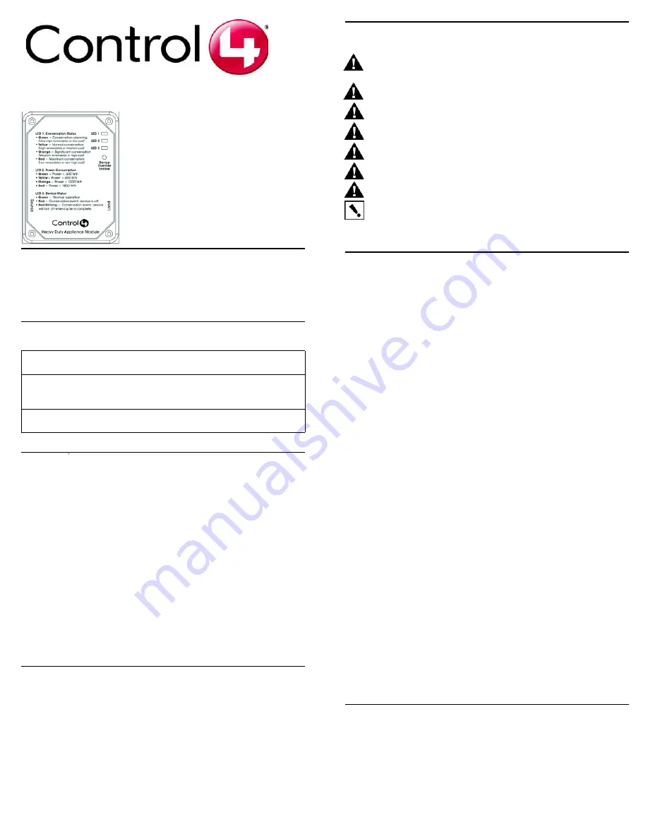
The Appliance Switch works with your Control4 home automation system
and utility companies to provide you with rate information and rules that you
can adjust to help minimize the power consumption of your key appliances
during high rate periods. The Appliance Switch switches LED colors to
indicate current status and power consumption (as described in Table 5 on
page 2). This information is also sent to the Home Controller as a system
event. System events can be used in programming either to notify home
owners of rate changes or to turn on or off an appliance.
Features
This appliance switch offers the following features:
•
Controls a single 120VAC 15-Amp or 20-Amp appliance (depending
on model of appliance switch) with not more than a 1 HP Motor.
•
Signals through LEDs on the Appliance Switch what conservation
level or power rate class you are currently in.
•
Signals to you how much power your appliance is comsuming by
changing colors on an LED.
•
Communicates with a Control4 home automation system.
•
Configurable through the Control4 home automation system.
•
Provides voltage, current, wattage, power factor, and total power
consumption through the Control4 home automation system.
Important Warnings and Information
WARNING!
The Switchable Appliance Module is rated for a combined load as
listed in the table above; do not plug in devices that exceed these ratings, either
alone or in combination.
WARNING!
Improper use or installation can cause SERIOUS INJURY,
DEATH, or LOSS/DAMAGE OF PROPERTY.
WARNING!
Install in accordance with all national, state, and local electrical
codes.
WARNING!
This product generates heat. The room must have adequate
ventilation or the ability to dissipate heat effectively.
WARNING!
This product must be grounded in accordance with the National
Electrical Code (NEC) requirements.
WARNING!
Use this product only in dry locations.
CAUTION!
This product is for residential use only.
IMPORTANT!
Using this product in a manner other than outlined in this
document voids your warranty. Further, Control4 is
not
liable for any damage
incurred because of the misuse of this product. See “Limited 2 Year Warranty”
on page 2.
Install and Configure the Appliance Switch
The 15-Amp or 20-Amp Appliance Switch controls only a single appliance
power load. The following steps guide you through the setup of this
appliance switch. Configuring this switch requires that you follow the
instructions in your Control4 Composer software to recognize and configure
this device.
To install and configure the appliance switch:
1
When choosing a location to plug in the appliance switch, consider the
following: (1) Avoid placing it near other household devices that can
cause interference, such as microwave ovens or cordless telephones
utilizing the 2.4 GHz frequency band; (2) Place within range of other
ZigBee devices to facilitate communication on the Control4 system.
2
Plug the appliance switch 3-prong power cord into a wall outlet.
3
Plug the appliances 3-prong power cord into the female power cord of
the appliance switch.
4
On a PC connected to the system, start the Composer software
provided (Composer 1.6 with the AMI Add-On Pack) to configure the
appliance switch for this installation. (Refer to the Composer online help
for general instructions on configuring a device.)
a.
In the System Design view, verify that
Wireless Outlet Switch w/
Override
is displayed in the project tree. If not, go to Search tab
(Local Database) and select:
•
Device Type:
Other
•
Manufacturer:
Control4
to display the Control4 driver options ERT Meter Bridge and
ENERGY_OUTLET (appliance switch), then add
ENERGY_OUTLET to the project tree. Once added, this device
displays in the tree as Wireless Outlet Switch w/ Override.
b.
In the Connections view, select the Network tab.
c.
In the IP Network Connections list, select Wireless Outlet Switch
w/ Override and then click Identify.
d.
Follow the screen prompt to identify this device: At the appliance
switch, press the Override buttom 4 times. When successfully
identified, a network address displays for this device.
Troubleshooting
If the appliance switch does not power its attached device:
•
Ensure all plugs are fully inserted.
•
Ensure the device you plugged into the appliance switch works
when plugged into a conventional AC wall outlet.
•
Ensure the circuit breaker is not turned Off or tripped.
•
Verify that the appliance switch is identified in Composer.
•
Check Composer setting (“LED-Enabled/Disabled) if at least one
LED is not lit.
Power
Requirements: 120VAC, 50/60 Hz, 1.7 W
Load Ratings: Model C4-AM15-120-Z-B: 120VAC, 1800 W
Model C4-AM20-120-Z-B: 120VAC, 2400 W
Motor: 1 HP
Operating
Temperature:
All load ratings are based on an ambient temperature of
25 degrees Celsius.


