Application manual for YRB-4EML-31S safety relay
Contrinex AG Industrial Electronics
12
d
2.2.4 Dividing the safety function into subsystems
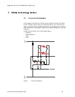
In the next step, a safety-related block diagram must be created for further evaluation. As a
rule, a safety function consists of sensor - logic - actuator. In the simplest case, each one is a
subsystem. These subsystems are connected in series to form the overall safety function.
L
I
m
L
I
m
O
Figure 3
Safety-related block diagram (according to EN 13849-1)
2.2.5
Determination of the achieved PL for each subsystem
A characteristic value when determining the performance level is the PFH
d
value, the
statistical
“probability of a dangerous failure per hour”. The safety characteristics can be
found in the FUNCTIONAL SAFETY CHARACTERISTICS data sheet or the SISTEMA
library.
The diagram below shows the basic relationship between PL and the safety characteristics
category, DC, and MTTF
d
.
PFH
D
a
-5
MTTF
d
low
10
b
MTTF
d
10
-6
medium
c
MTTF
-7
10
high
d
-8
10
e
Cat. B
Cat. 1 Cat. 2
Cat. 2
Cat. 3
Cat. 3
Cat. 4
Dc
avg
none
Dc
avg
none
Dc
avg
low
Dc
avg
medium
Dc
avg
low
Dc
avg
medium
Dc
avg
high
Figure 4
Relationship between PL, category, DC, and MTTFd
(according to EN 13849-1)
The category is an important parameter when determining the PL. The category term has
been taken from the previous standard EN 954-1. The requirements for the categories are
listed below.


