


W415-1080 / B / 08.28.13
47
IOM
18.0 AIR
FLOW
For proper furnace operation, air
fl
ow over the heat exchanger is of utmost importance. Insuf
fi
cient air
fl
ow ac-
celerates metal fatigue and possible failure in the heat exchanger, and decreases ef
fi
ciency. Excessive air
fl
ow
promotes accelerated corrosion of the heat exchanger.
IMPORTANT:
DO NOT BYPASS THIS STEP OF THE
START UP PROCEDURES.
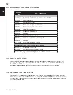
18.1 TEMPERATURE RISE CHECK
TABLE 1 - RANGE OF TEMPERATURE RISE
Furnace Models
Temperature Rise
ALL
High Fire (HF) 35 - 65°F (20 - 36°C)
Low Fire (LF) 20 - 50°F (11 - 28°C)
H12.15.4
When the duct system is complete and the air
fi
lter or
fi
lters are in place, determine if the air
fl
ow is correct for both
low and high
fi
re input rates.
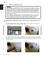
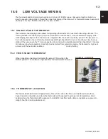
1. Insert a duct thermometer in the supply air duct. The thermometer should be placed as close as practical to
the furnace, but out of the “line of sight” of the heat exchanger (this prevents false readings owing to radi-
ant heat). Ensure that the thermometer location is within the duct air stream. Avoid locations such as the
inside radius of an elbow, etc.
2. Insert a duct thermometer in the return air duct as close to the furnace as practical. Ensure that the ther-
mometer location will be unaffected by humidi
fi
er bypass ducts, etc. Choose a location well within the main
air stream.
3. Operate the furnace long enough to obtain steady state conditions at both input rates (High Fire and Low Fire).
4. When the two thermometers have stabilized, usually within 5-8 minutes, compare the two readings. Sub-
tract the return air temperature from the supply air temperature. The difference is the temperature rise, also
called
∆
T.
5. Compare the measured
∆
T to the temperature rise range shown on the rating plate.
Unless stated differently on the rating plate, the temperature rise should normally range between 35° to 65°F (20 to
36°C) High Fire, 20° to 50°F (11 to 28°C) Low Fire. When adjusting the temperature rise, the ideal temperature rise
is approximately mid-range.
If the measured
∆
T is above the
approved temperature range, there
is too little air
fl
ow. It must be in-
creased by selecting the appropriate
“HEAT” jumper setting, removing re-
strictions in the ductwork, or adding
supply or return ductwork.
If the measured
∆
T is too low, there
is too much air
fl
ow.
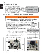
NOTE
Moving the ADJUST jumper from the NORM position to the (+) or (-) position
will increase or lower the CFM by 15%. Air
fl
ow based on approximately 375
CFM/Ton. Refer to Figure 39.
TABLE 7B - AIR FLOW (Y2-HIGH COOL)
ECM 2.3
ESP 0.1” to 1.0” w.c.
Input
Max A/C
ADJUST
COOL
CFM
Tonnage
Jumper
Jumper
60000
3 Ton
NORM
A
1125
B
940
C
750
D
560
80000
3 Ton
NORM
A
1125
B
940
C
750
D
560
100000
5 Ton
NORM
A
1750
B
1400
C
1050
D
700
120000
5 Ton
NORM
A
1750
B
1400
C
1050
D
700
TABLE 7A - AIR FLOW (Y1-LOW COOL)
ECM 2.3
ESP 0.1” to 1.0” w.c.
Input
A/C
ADJUST
COOL
CFM
Tonnage
Jumper
Jumper
60000
N/A
NORM
A
675
B
564
C
N/A
D
N/A
80000
N/A
NORM
A
675
B
564
C
N/A
D
N/A
100000
N/A
NORM
A
1050
B
840
C
630
D
N/A
120000
N/A
NORM
A
1050
B
840
C
630
D
N/A
H12.1.5


