Continental Hydraulics CEM-MS-A Installation Manual Download Page 8

Continental Hydraulics Installation Manual

Page 8 of 15

CEM-MS-A

CHI 1013478   Jan 2013

Adjust module output to match valve requirements:

The CEM-MS module has a 0 to +/-10v differential output.  This output is designed to directly 
interface to proportional valves with on board electronics.

This output signal may be configured to more closely match the valve characteristics.  The 
parameters used to adjust the output signal include:

MAX:A and MAX:B
MIN:A and MIN:B
TRIGGER

MAX:A and MAX:B are set with software as a percentage of the 10v output.  MAX:A and 
MAX:B are set at 100% (10000) for a valve that has a 10v input rating.  To reduce the maximum 
flow from a valve with a spool that is too large, set MAX to a number less than 100%.  Valid range 
is from 5000 to 10000.  Default is 10000.  Units are 0.01%

MIN:A and MIN:B are adjusted via software for the purpose of deadband elimination.  A valve 
with a minimum control point (cracking point) will give best performance if this deadband is 
eliminated.  Valid range is 0 to 5000.  Default is 0.  Units are 0.01%.

Example:  A directional control valve has an input range of 0 to +/-10v.  The valve is 

factory calibrated to begin flow at 1v, and max flow is at 10v.  Adjust the CEM-SA parameters:

MAX:A = 10000  (100% of +10v)
MIN:A =    900  (9% of 10v = +0.9v)
MAX:B = 10000  (100% of -10v)
MIN:B =    900  (9% of -10v = -0.9v)
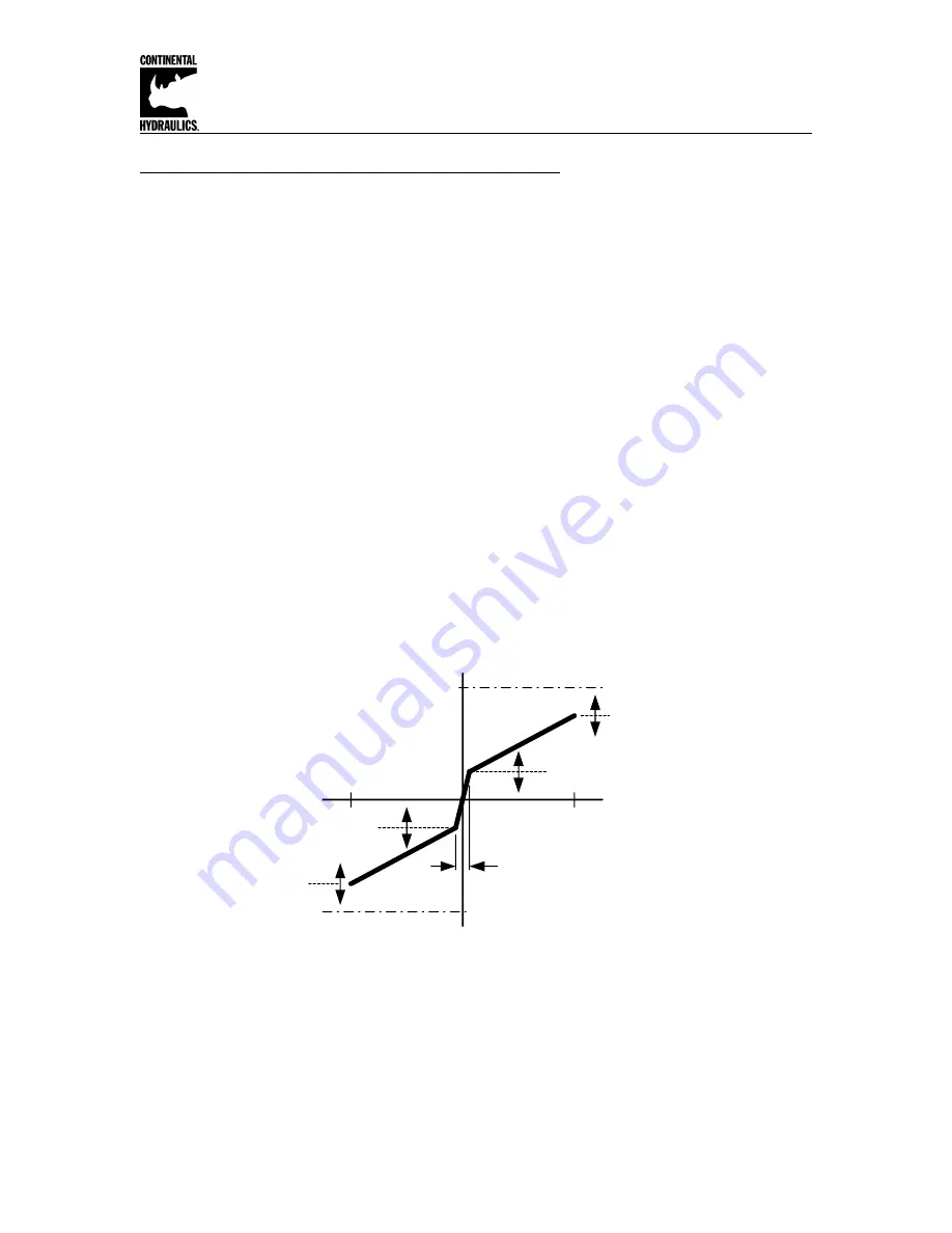
                        

Min A =

% of Range

Max A =

% of Range

Voltage Output 

+

10v

Trigger = % of Output

Module output  +100%

Module output 

-

100%

Min B =

% of Range

Max B =

% of Range

Voltage Output 

-

10v

TRIGGER and MIN can be used together to optimize valve performance near zero.

When using a proportional valve with an overlap spool, adjust TRIGGER to 200 (2%), and MIN:A 
and MIN:B to slightly less than the “crack point” of the valve.

Summary of Contents for CEM-MS-A

Page 1: ...o a variety of system requirements All variables are user adjusted with easy to use software on your Microsoft Windows laptop Control variables are stored in non volatile memory internal to the module...

Page 2: ...ronized Feedback Position ws v 12 Ground Differential Input on Control Valve 3 DC DC 12 to 24v 0v 4 Profile 13 11 Command Position Control Synch xk Synch active w xd 0 to 10v or 4 to 20 mA 0 to 10v 0...

Page 3: ...t for protection from the local environment Ensure there is adequate free space around the module to allow for cooling air flow This module is designed to snap onto an industry standard 35mm DIN rail...

Page 4: ...STROKE load distance A A and A B ramping times VELO internally controlled velocity D A and D B Deceleration start point STROKE defines the full motion Valid options are 10 to 10000 Default is 100 Uni...

Page 5: ...th the VRAMP parameter VRAMP valid values are 1 to 5000 Default is 50 Units are msec Deceleration characteristic is controlled by the CTRL parameter CTRL valid options are LIN SQRT1 and SQRT2 Default...

Page 6: ...Run GL Active 8 7 5 13 14 6 15 16 14 6 13 CEM MS Master CEM MS Master 15 16 Up to four axis may be synchronized in the Master Slave mode Master Slave control theory will always have the slave followin...

Page 7: ...rol GL P GL T1 GL P and GL T1 parameters GL P sets the synchronization gain As with the basic single axis control reducing the braking distance will increase the system gain but has the potential to p...

Page 8: ...from 5000 to 10000 Default is 10000 Units are 0 01 MIN A and MIN B are adjusted via software for the purpose of deadband elimination A valve with a minimum control point cracking point will give best...

Page 9: ...pool valve An overlap spool valve will do a better job of holding the load in a static condition An overlap valve can be commanded to go to center In this center condition the valve port to port leaka...

Page 10: ...nd Analog Voltage Source Ground Referenced Voltage PLC Digitial Motion Controller etc Gnd An external position command voltage source must be referenced to ground for proper operation 13 11 24v 3 4 Po...

Page 11: ...t feedback 14 11 24v 3 4 Power Supply Gnd Line AC DC Gnd 4 to 20mA Position Transmitter A Line AC DC Loop Monitor optional Power Supply 6 11 24v 3 4 Power Supply Gnd AC DC Gnd CEM MS Master CEM MS Sla...

Page 12: ...t C Output of this scaling equation must always be equal to the module native input range 0 to 10v Input can be any voltage within this 10v range The ratio of A B allows for a decimal scaling factor T...

Page 13: ...will disable When the error is corrected the module will resume function without cycling ENABLE If the module has been configured to accept current commands a command value outside of 4 to 20 mA will...

Page 14: ...th GL Active low off the module will operate as a single axis closed loop position control module functionally equivalent to a CEM SA InPOS pin 2 digital output InPOS pin 2 is a digital output that is...

Page 15: ...tus Steady on Synch error is within InPOS tolerance Off Synch error is outside InPOS tolerance Parameter monitoring using software The following parameters may be monitored in real time using Windows...

Reviews: