12
W415-0861 / A / 02.10.11
37
"
3"
13 ½”
5 ½”
36 ½”
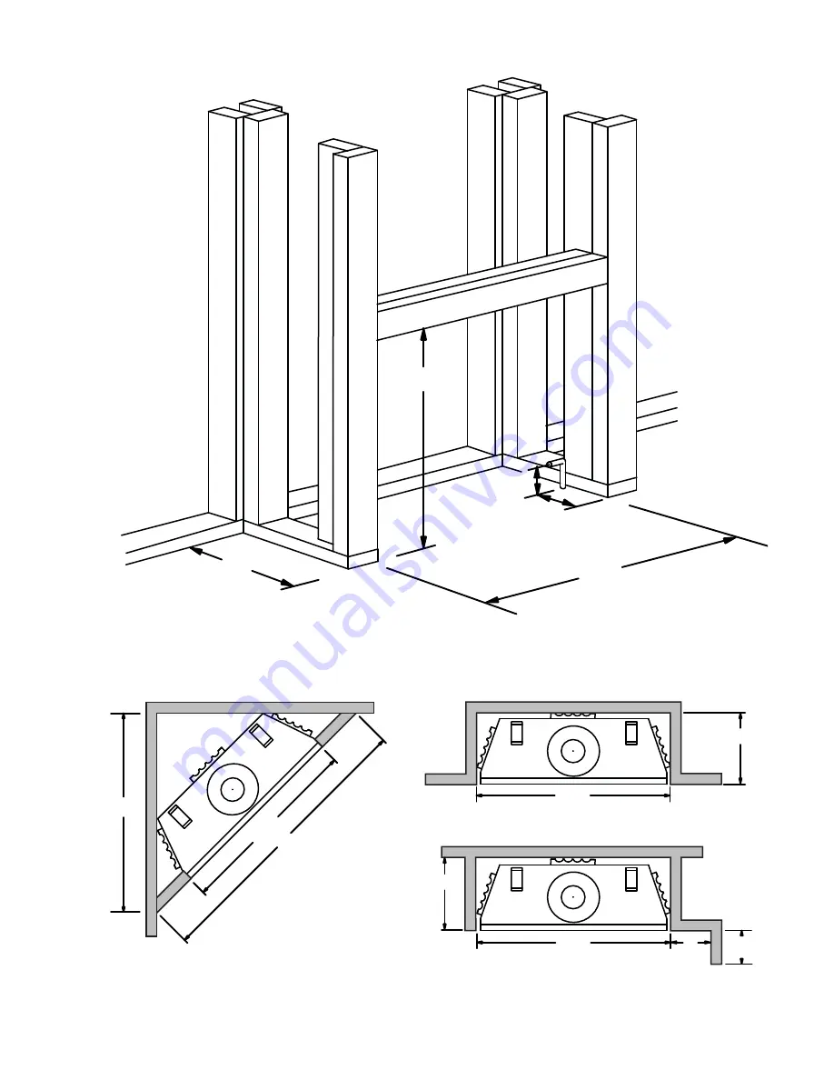
5.1 MINIMUM CLEARANCE TO COMBUSTIBLES
36
1
/
2
52"
3
4
6
2' MIN.
13
INSIDECHASE
OUTSIDE
CHASE
Page 1: ...S Do not try to light any appliance Do not touch any electrical switch do not use any phone in your building Immediately call your gas supplier from a neighbour s phone Follow the gas supplier s instructions If you cannot reach your gas supplier call the fire department Installation and service must be performed by a qualified installer service agency or the supplier If the information in these in...
Page 2: ...TAT 10 5 0 FRAMING 11 5 1 MINIMUM CLEARANCE TO COMBUSTIBLES 12 5 2 MINIMUM MANTEL CLEARANCES 13 5 3 NAILING TAB INSTALLATION 13 6 0 FINISHING 14 6 1 DOOR INSTALLATION REMOVAL 14 6 2 LOG PLACEMENT 15 6 3 CHARCOAL EMBERS 16 6 4 GLOWING EMBERS 16 6 5 LOGO PLACEMENT 16 6 6 LOUVRE INSTALLATION 16 7 0 OPTIONAL BLOWER INSTALLATION 17 8 0 OPERATION 19 9 0 ADJUSTMENTS 20 9 1 PILOT BURNER ADJUSTMENT 20 9 2 ...
Page 3: ...es see LOUVRE INSTALLATION section Glass see DOOR GLASS REPLACEMENT section Door see DOOR INSTALLATION REMOVAL section Logo see LOGO PLACEMENT section Logs see LOG PLACEMENT section Vent see VENTING section Rating plate see RATING PLATE INFORMATION section ...
Page 4: ...astened to the floor Any safety screen or guard removed for servicing must be replaced prior to operating the appliance This appliance is a vented gas fired appliance Do not burn wood or other materials in this appliance It is imperative that the control compartments burners and circulating blower and its passageway in the appliance and venting system are kept clean The appliance and its venting s...
Page 5: ...THE PILOT WHETHER FOR THE FIRST TIME OR IF THE GAS SUPPLY HAS RUN OUT WITH THE GLASS DOOR OPENED OR REMOVED PROVIDE ADEQUATE CLEARANCE FOR SERVICING AND OPERATING THE APPLIANCE PROVIDE ADEQUATE VENTILATION NEVER OBSTRUCT THE FRONT OPENING OF THE APPLIANCE OBJECTS PLACED IN FRONT OF THE APPLIANCE MUST BE KEPT A MINIMUM OF 48 FROM THE FRONT FACE OF THE UNIT SURFACES AROUND AND ESPECIALLY ABOVE THE A...
Page 6: ... fans or blowers If an optional fan or blower is installed the junction box must be electrically connected and grounded in accordance with local codes use the current CSA C22 1 Canadian Electrical Code in Canada or the ANSI NFPA 70 National Electrical code in the United States We suggest that our gas hearth products be installed and serviced by professionals who are certified in the U S by the Nat...
Page 7: ... CONTACTAVEC LES FLAMMESAUTRE QUE CELUI QUI EST FOURNIAVEC CETAPPAREIL PAR LE FABRICANT THE APPLIANCE MUST BE VENTED USING B VENT SEE OWNERS INSTALLATION MANUAL FOR VENTING SPECIFICS L APPAREIL DOIT EVACUER SES GAZ EN UTILISANT L EVENT B REFERER AU MANUEL D INSTALLATION DE PROPRIETAIRE POUR L EVACUATION PRECISE ELECTRICAL RATING CLASSIFICATION 115V 0 82AMP 60HZ OPTIONALFAN KIT ENSEMBLE DE VENTILAT...
Page 8: ...B vent and an insulated chase is recommended Under extreme vent configurations allow several minutes 5 15 for the flame to stabilize after ignition Provide a means for visually checking the vent connection to the appliance after the appliance is installed TAMPERING WITH THE SAFETY SWITCH CAN RESULT IN CARBON MONOXIDE POISONING AND POSSIBLE DEATH WARNING This thermally activated switch located in f...
Page 9: ...e appliance blower off if so equipped B Set controls to high and light the appliance C Wait 5 minutes Light a match and hold to the front of the draft hood Venting action is satisfactory if smoke and flames are drawn into the draft hood Venting action is unsatisfactory if the smoke spills back and the flame splays outward If venting action is unsatisfactory turn off the appliance wait 10 minutes a...
Page 10: ...S CONTROL WHEN ATTACHING GAS SUPPLY PIPE TO PREVENT DAMAGING GAS LINE ALWAYS LIGHT THE PILOT WHETHER FOR THE FIRST TIME OR IF THE GAS SUPPLY HAS RUN OUT WITH THE GLASS DOOR OPENED OR REMOVED PURGING OF THE GAS SUPPLY LINE SHOULD BE PERFORMED BY A QUALIFIED SERVICE TECHNICIAN ASSURE THAT A CONTINUOUS GAS FLOW IS AT THE BURNER BEFORE CLOSING THE DOOR ENSURE ADEQUATE VENTILATION FOR GAS AND ELECTRICA...
Page 11: ...ATE GLASS OR PLASTERS OR ANY COMBINATION THEREOF ARE SUITABLE MATERIALS THAT ARE REPORTED AS PASSING ASTM E 136 STANDARD TEST METHOD FOR BEHAVIOUR OF MATERIALS IN A VERTICAL TUBE FURNACE AT 750 C AND UL763 SHALL BE CONSIDERED NON COMBUSTIBLE MATERIALS MINIMUM CLEARANCE TO COMBUSTIBLES MUST BE MAINTAINED OR A SERIOUS FIRE HAZARD COULD RESULT THE APPLIANCE REQUIRES A MINIMUM ENCLOSURE HEIGHT MEASURE...
Page 12: ...12 W415 0861 A 02 10 11 37 3 13 5 36 5 1 MINIMUM CLEARANCE TO COMBUSTIBLES 3 6 1 2 5 2 36 3 4 36 1 2 36 1 2 6 2 MIN 13 1 2 INSIDE CHASE OUTSIDE CHASE 13 1 2 ...
Page 13: ... 2 0 4 2 4 10 8 12 12 8 10 7 MANTLE 6 2 4 6 7 TOP OF UNIT COMBUSTIBLE MATERIALS 2x4 2 4 5 3 NAILING TAB INSTALLATION 55 1A A Attach the nailing tabs to the corner posts using the 2 sheet metal screws sup plied Secure through the centre of the top and bottom slots in the nailing tab and then through the existing holes in the corner posts If there are no existing holes follow these instructions B To...
Page 14: ... OPENINGS LOUVRES OPENINGS OPERATION OF LOUVRES OR DOORS OR ACCESS FOR SERVICE OBSERVE ALL CLEARANCES WHEN APPLYING COMBUSTIBLE MATERIALS BEFORE DOOR IS REMOVED TURN THE APPLIANCE OFF AND WAIT UNTIL APPLIANCE IS COOL TO THE TOUCH DOORS ARE HEAVY AND FRAGILE SO HANDLE WITH CARE 75 1 WARNING RISK OF FIRE NEVER OBSTRUCT THE FRONT OPENING OF THE APPLIANCE THE FRONT OF THE APPLIANCE MUST BE FINISHED WI...
Page 15: ...g the heat activated curing process TAB SIDE VIEW A Place the back log 1 onto the log support tray and in front of the tabs The tabs maintain an air space between the log and firebox back to facilitate com bustion air flow Ensure that the back of the log rests against the brackets on the back wall of the firebox 6 2 LOG PLACEMENT B Move the two small logs 2 3 into posi tion lining up the studs loc...
Page 16: ...embers along the front and sides of the log support tray in a realistic manner Fine dust found in the bottom of the bag should not be used NOTE Charcoal embers are not to be placed on the burner A B C SLOT A B C CLIPS CENTRE SLOT TAB SLOT HINGE CLIP 57 3 UPPER LOUVRES Insert the louvre tabs into the slots located at the top left and right corners of the unit LOWER LOUVRES Insert the hinge clips in...
Page 17: ... United States If the appliance was not previously equipped with a blower Route a grounded 2 wire 60hz power cable to the receptacle junction box At this point it must be strain relieved and insulated The three slots on the blower mounting bracket allow ease of adjustment when attaching the blower For a quiet running blower do not allow the assembly to sit on the firebox base Slide the vibration r...
Page 18: ...ower is thermally activated when turned on it will automatically start approximately 10 minutes after lighting the appliance and will run for approximately 30 45 minutes after the appliance has been turned off Use of the fan increases the output of heat Drywall dust will penetrate into the blower bearings causing irreparable damage Care must be taken to prevent drywall dust from coming into contac...
Page 19: ...lot burner to be lit until the thermo couple has cooled Allow approximately 60 seconds for the thermocouple to cool When lighting and re lighting the gas knob cannot be turned from pilot to off unless the knob is depressed slightly 1 Stop Read the above safety information on this label 2 Turn off all electric power to the appliance 3 Turn the gas knob clockwise to off 4 Wait five 5 minutes to clea...
Page 20: ...Check that main burner is operating on HI AFTER TAKING PRESSURE READINGS TIGHTEN SCREWS FIRMLY TO SEAL DO NOT OVER TORQUE LEAK TEST 39 3 P I P I L O T N O L O T HI L O F F O A B PILOT SCREW PILOT BURNER THERMOCOUPLE THERMOPILE This appliance has an air shutter that has been factory set open according to the chart below Regardless of venturi orientation closing the air shutter will cause a more yel...
Page 21: ...he area surrounding the logs clean by vacuuming or brushing at least once a year 3 Check to see that all burner ports are burning Clean out any of the ports which may not be burning or are not burning properly 4 Check to see that the pilot flame is large enough to engulf the flame sensor and or thermocouple thermopile as well as reaches the burner 5 Replace the cleaned logs rocks or glass Failure ...
Page 22: ...ASS UNTIL COOLED CARE MUST BE TAKEN WHEN REMOVING AND DISPOSING OF ANY BROKEN DOOR GLASS OR DAMAGED COMPONENTS BE SURE TO VACUUM UP ANY BROKEN GLASS FROM INSIDE THE APPLIANCE BEFORE OPERATION DO NOT STRIKE SLAM OR SCRATCH GLASS DO NOT OPERATE APPLIANCE WITH GLASS REMOVED CRACKED BROKEN OR SCRATCHED 56 1 6 1 If the appliance is equipped with plated parts you must clean fingerprints or other marks f...
Page 23: ...R PERSONAL INJURY WARNING COMMON COMPONENTS REF NO PART NO DESCRIPTION 1 W357 0001 PIEZO IGNITOR 2 W680 0004 THERMOPILE 3 W680 0005 THERMOCOUPLE 4 W010 0764 BURNER 5 W010 0800 NATURAL GAS PILOT ASSEMBLY 5 W010 0801 PROPANE GAS PILOT ASSEMBLY 6 W660 0021 SAFETY SWITCH 7 W660 0007 HI LIMIT SWITCH 8 W455 0069 NATURAL GAS PILOT INJECTOR 8 W455 0068 PROPANE GAS PILOT INJECTOR 9 W725 0025 NATURAL GAS VA...
Page 24: ...0 0005 THERMOSTAT 110V 33 GA 72 HOT AIR EXHAUST KIT 34 GA 70 EXTENSION KIT 5FT 35 COIK CONTINENTAL ORNAMENTAL INSETS BLACK 35 COISS CONTINENTAL ORNAMENTAL INSETS SATIN CHROME 36 DK36 R DOOR KIT RECTANGULAR BLACK 37 DK36 A DOOR KIT ARCHED BLACK 38 DK36 W DOOR KIT WEBBED BLACK 38 DK36 WG DOOR KIT WEBBED GOLD PLATED 39 DK36 N DOOR KIT NORTHERN BLACK 39 DK 36 NPW DOOR KIT NORTHERN PEWTER 40 W175 0159 ...
Page 25: ...25 W415 0861 A 02 10 11 5 3 8 2 14 13 36 38 37 34 1 29 4 9 15 31 33 6 7 25 18 23 24 22 20 21 19 35 ...
Page 26: ...knob is on HI wall switch thermostat is on Thermostat or switch is defective Connect a jumper wire across the wall switch terminals if main burner lights replace switch thermostat Wall switch wiring is defective Disconnect the switch wires connect a jumper wire across terminals 1 3 if the main burner lights check the wires for defects and or replace wires Main burner orifice is plugged Remove stop...
Page 27: ...ure increase fresh air supply Carbon is being deposited on glass logs or combustion chamber surfaces Air shutter has become blocked Ensure air shutter opening is free of lint or other obstructions Flame is impinging on the logs or combustion chamber Check that the logs are correctly positioned Open air shutter to increase the primary air Check the input rate check the manifold pressure and orifice...
Page 28: ...ons such as rooftops buildings nearby trees hills mountains inadequate vents or ventilation excessive venting configurations insufficient makeup air or negative air pressures which may or may not be caused by mechanical systems such as exhaust fans furnaces clothes dryers etc Any damages to appliance combustion chamber heat exchanger brass trim or other components due to water weather damage long ...
Page 29: ...29 W415 0861 A 02 10 11 14 0 SERVICE HISTORY 43 1 ...
Page 30: ...30 W415 0861 A 02 10 11 44 1 15 0 NOTES ...
Page 31: ...31 W415 0861 A 02 10 11 44 1 ...
Page 32: ...32 W415 0861 A 02 10 11 44 1 ...