background image

Contemporary 

Research    

12 


232-STSi PAL TV Tuner


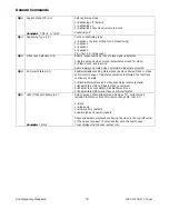
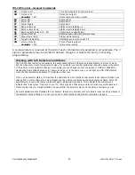
RS-232 Control – General Commands

XX 

Mute A/V off 

Turn A/V outputs on at previous level 

XM 

Mute A/V on 

Example:  

‘>XM’ 

Mutes A/V outputs 

Mutes audio and video outputs 

P0 

Power Off 

Same as XM 

P1 

Power On 

Same as XX 

PT 

Power Toggle 

Same as XT 

VU 

Ramp volume up 

Starts volume ramping up 

VD 

Ramp volume down 

Starts volume ramping down 

VL 

Ramps volume to level (0 – 63) 

Sets volume to specific level 

VX 

Volume Mute off 

Restores audio volume to previous level 

VV 

Stop volume ramp 

Stops volume ramping 

VT 

Toggle Volume Mute 

Alternates audio mute on and off 

VM 

Volume Mute on 

Example:

  ‘

>VM’ 

Turns off audio outputs 

Mutes audio outputs 


A carriage return is required at the end of each command and is assumed in all examples. The ‘=’ 

sign for parameters may be omitted if desired, though it is helpful for clarity in checking 

programming. 


Working with A/V Detectors and Status 

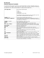
The 232-STSi has two active A/V sensors, the audio sensor detects if the station in broadcasting in stereo or mono, 
and the video sensor looks for presence of video. If you desire, your control system can respond whenever the status 
of the audio or video detectors change. For example, you can change the text of a button to MONO or STEREO by 
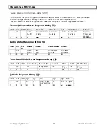
tracking the Audio Status Response (V), shown on page 13. In the same way, you can light up a NO VIDEO button, 
when the Channel/Source Response (T) indicates a video loss. 

 
If you use AV detector status, it’s important to understand how the functions will operate in the real world. When you 
change from a stereo channel to a mono broadcast, the V string will first show the audio status as stereo. When the 
audio detector locks in, the status will be sent again, indicating mono audio. This is similar to the stereo/mono 
indicator and “blue screen” functions on your TV, there may be a little delay, and the function may switch back and 
forth a couple times for marginal stations. So expect that the detectors may send the string a few times as well. 

 
As most applications aren’t tracking the A/V sensors, the tuner is normally set not to send a response string whenever 
the detectors sense a change. You can turn on one or both functions using the Q3 command on page 9.


Summary of Contents for 232-STSI

Page 1: ...rt Road Suite 113 Dallas TX 75252 Phone 972 931 2728 Toll Free 888 972 2728 Fax 972 931 2765 E Mail Sales crwww com Website www crwww com Product Manual 232 STSi Stereo PAL TV Tuner S Video Version 6...

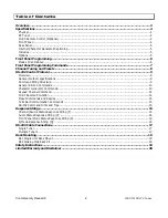
Page 2: ...ions 9 Command String Structure 9 General RS 232 Commands 10 Character Generator Commands 13 Keypad Channel Command 14 IC RC Remote Emulation 14 Preset Commands and Replies 15 Terminal Communication C...

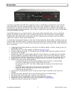
Page 3: ...ware available from www crwww com Features intelligent auto tuning of TV frequencies with the ability to save channel presets that include the frequency and TV Standard Outputs S Video signal for impr...

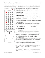
Page 4: ...ypad Channel selection press Enter to select channel Volume Up Down and Mute Channel Channel Up Down Presets Up Down Left Right and Top keys search add and delete channel presets CC Selects Closed Cap...

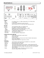
Page 5: ...r stereo mono and dual modes Stereo Dual Total Harmonic Distortion THD 0 6 maximum 0 3 typical Response 30Hz to 14KHz Channel Separation 40dB minimum 45dB typical Mono Total Harmonic Distortion THD 0...

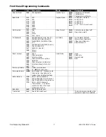
Page 6: ...le in this mode 5 Changes are saved in non volatile memory as they are entered 6 The Volume up down buttons scroll through programming modes 0 through 9 and 10 7 The Channel up down buttons scroll thr...

Page 7: ...NICAM 3 9 SECAM L Rev 6 2 Future Future AV Status 13 0 13 1 13 2 13 3 No AV status default Stereo Mono status only Video Loss status only Both status sent Panel Lockout 4 0 4 1 4 2 4 3 4 4 4 5 4 6 4...

Page 8: ...tuner will display on screen text to confirm which standard is active The first standard to appear is the current setting PAL B G H A2 PAL B G H NICAM PAL D K NICAM PAL I NICAM Search for Broadcasts P...

Page 9: ...2K baud 8 data bits No parity and 1 stop bit Factory default is 9600 baud Unit 1 All settings are saved to NVRAM in the 232 STSi The tuner will accept non standard RS 232 control such as voltage that...

Page 10: ...re selected Q3 AV Detect Status 0 3 Enables disables sending status response when Stereo Mono or Video Loss Detect changes Only status operation is affected the functions continue to operate 0 Disable...

Page 11: ...annel status Example ST Unit sends T Channel Source status string Returns Channel Source status response string SV Request A V status Unit sends V Audio status string TR Set Tune Ring TR Not applicabl...

Page 12: ...in stereo or mono and the video sensor looks for presence of video If you desire your control system can respond whenever the status of the audio or video detectors change For example you can change...

Page 13: ...rrent channel label on screen for about 10 seconds DG row column Moves the cursor to the specified row and column position If row is 0 then row will not be changed and if column is 0 then column will...

Page 14: ...er 3 seconds with no other key the selected channel will be tuned to Optionally you can have an Enter key send the command KC or KT to select the channel immediately Using the KD command can cancel a...

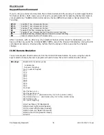
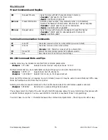
Page 15: ...l number and software version Z Zap Reconfigures unit for all factory default settings RS 232 Command Hints and Tips Leading zeros may be included or omitted from command parameters Example TC 009 Sel...

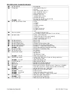
Page 16: ...1 Video Mute N A Video Present Reference 1 9 U On M Off Current Channel 3 digits U Unmuted M Mute 2 digits N No Video Y Video Frequency TV Standard xxx xx xx 1 T U 008 U xx Y 271 25 02 Audio Status Re...

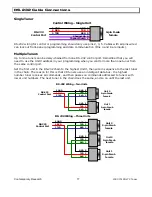
Page 17: ...rt Set the first unit in the RS 232 chain to the highest Unit then wire in sequence to the last tuner in the chain The reason for this is that CR tuners use an intelligent data bus the highest number...

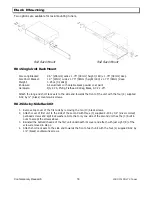
Page 18: ...e four 4 supplied 8 32 by black countersunk screws RK2 Side by Side Rack Kit 1 Remove top cover of the first unit by removing the ten 10 black screws 2 Attach cover of first unit to the side of the se...

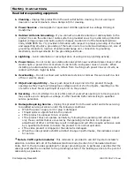
Page 19: ...ctric shock 7 Object and Liquid Entry Never push objects of any kind into this product through openings as they may touch dangerous voltage points or short out parts resulting in a fire or electric sh...

Page 20: ...mages are sought or a claim is made under this warranty or as a tort claim including negligence and strict product liability a contract claim or any other claim This limitation of liability cannot be...

Reviews: