background image

5. BIOS Setup 


VPC-500 Series User’s Manual 


31


Configuration 

Specify the detailed system functions. 

Aptio Setup Utility - Copyright (C) 20xx American Megatrends, Inc. 

Main 

Configuration 

Security 

Boot 

Save & Exit 


CPU Configuration 


Chipset Configuration 


LAN Configuration 


Graphics Configuration 


PCI/PCIE Configuration 


SATA Configuration 


USB Configuration 


Power Control Configuration 


TPM Configuration 


Super IO Configuration 


H/W Monitor 


Serial Port Console Redirection 


→←

:Select Screen 

↑↓

:Select Item 

Enter:Select 
+/-:Change Opt. 
F1:General Help 
F2:Previous Values 
F3:Optimized Defaults 
F4:Save & Exit 
ESC:Exit 


Version x.xx.xxxx. Copyright (C) 20xx American Megatrends, Inc. 


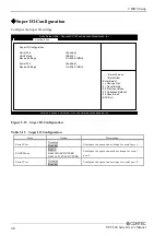
Figure 5.3    Configuration 


CPU Configuration 

Configure the CPU settings. 

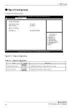
Chipset Configuration 

Configure the Chipset settings. 

LAN Configuration 

Configure the LAN controller settings. 

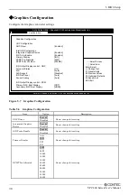
Graphics Configuration 

Configure the Graphics controller settings. 

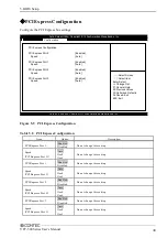
PCI/PCIE Configuration 

Configure the PCI bus and the PCI Express bus settings. 

SATA Configuration 

Configure the SATA controller settings. 

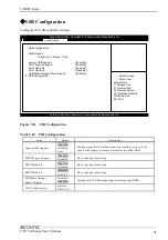
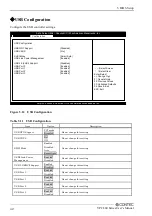
USB Configuration 

Configure the USB controller settings. 

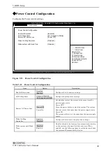
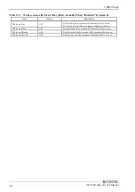
Power Control Configuration 

Configure the Power control settings. 

TPM Configuration 

Configure the TPM settings. 

Super IO Configuration 

Configure the Super IO settings. 

Summary of Contents for VPC-500

Page 1: ...FA PC VPC Series VPC 500 User s Manual CONTEC CO LTD...

Page 2: ...Product Configuration List VPC 500 76412B C01 VPC 500 76412B C05 Name Pcs PC 1 AC Power Cable 125VAC 1 1 Product guide 1 Warranty Certificate 1 Recovery Media 1 Product Configuration Image PC AC Power...

Page 3: ...onsidered in the preparation of this document Should you notice an omission or any questionable item in this document please feel free to notify CONTEC CO LTD 4 Regardless of the foregoing statement C...

Page 4: ...imensions 9 3 HARDWARE SETUP 13 Before Using the Product for the First Time 13 Hardware Setup 14 Attaching the Attachment Stand 14 Attaching the FG 15 Installation Requirements 16 4 EACH COMPONENT FUN...

Page 5: ...ation 31 CPU Configuration 33 Chipset Configuration 34 LAN Configuration 35 Graphics Configuration 36 PCI PCIE Configuration 38 PCI Express Configuration 39 SATA Configuration 40 USB Configuration 41...

Page 6: ...possible to attach to the VESA standard 75 x 75 100 x 100mm using the stand The silent design that held the noise in check It minimizes the noize while ensuring sufficient performance by abolishing a...

Page 7: ...Note For product information Contact your retailer if you have any technical question about a CONTEC product or need its price delivery time or estimate information How to Obtain Service For replacem...

Page 8: ...ld plated terminals such as the edge connectors of this product with your hands Doing so may lead to malfunctions or product failures Be sure to turn the power off before performing such an action Whe...

Page 9: ...e for the integrity of data on SSD Always remove the power cable from the power outlet before mounting or removing an expansion board and before connecting or disconnecting a connector Always remove t...

Page 10: ...e battery with an inappropriate type of battery may lead to explosions Dispose of used batteries according to the instructions in the instruction manual When disposing of a used battery follow the dis...

Page 11: ...1 Introduction 6 VPC 500 Series User s Manual...

Page 12: ...1 280 1 024 1 360 768 1 366 768 1 400 1 050 1 440 900 1 600 900 1 680 1 050 1 920 1 080 1 920 1 200 1 677 colors ReduceBlanking Storage SATA 2 5 SSD 32GB x1 Audio Realtek ALC892 controller HD Audio c...

Page 13: ...2 Installation Environment Requirements Model VPC 500 76412B C01 VPC 500 76412B C05 Ambient specifications Operating temperature 0 40 Storage temperature 10 60 Humidity 10 90 RH No condensation Floati...

Page 14: ...2 System Reference VPC 500 Series User s Manual 9 Physical Dimensions VPC 500 76412B C01 VPC 500 76412B C05 Main unit dimensions Figure 2 1 VPC 500 76412B C01 VPC 500 76412B C05 Main unit dimensions...

Page 15: ...erence 10 VPC 500 Series User s Manual Dimensions when attached to the stand Horizontal Installation Figure 2 2 VPC 500 76412B C01 VPC 500 76412B C05 Dimensions when attached to the stand Horizontal I...

Page 16: ...ertical installation Figure 2 3 VPC 500 76412B C01 VPC 500 76412B C05 Dimensions when attached to the stand Vertical installation 225 1 216 8 3 4 11 5 76 8 1 INPUT 100 240 VAC X XA MODEL VPC 500 76412...

Page 17: ...2 System Reference 12 VPC 500 Series User s Manual...

Page 18: ...steps 1 and 2 turn on the power If you find any abnormality after turning on the power turn it off and check to see if the setup has been performed properly STEP4 Set up BIOS By referring to Chapter...

Page 19: ...p Before you start be sure that the power is turned off Remove only those screws that are explained Do not move any other screw Attaching the Attachment Stand 1 Attach the attachment stand Do not atta...

Page 20: ...Manual 15 Attaching the FG 1 Use screws to attach the FG Figure 3 2 Attaching the FG Screw holes may be damaged if screws are tightened with a torque greater than the specified torque The specified t...

Page 21: ...onment requirement by making space between the product and device that generates heat or exhaust air Figure 3 3 Installation Image Note that even though the ambient temperature is within the specified...

Page 22: ...t Temperature increase caused by long term usage may result in operational malfunction or other problems Vertical orientation Figure 3 5 Vertical orientation Attach the stand to the base of the produc...

Page 23: ...3 Hardware Setup 18 VPC 500 Series User s Manual...

Page 24: ...VPC 500 76412B C01 VPC 500 76412B C05 Front View Figure 4 1 VPC 500 76412B C01 VPC 500 76412B C05 Component Name 1 2 Rear View Figure 4 1 VPC 500 76412B C01 VPC 500 76412B C05 Component Name 2 2 USB2...

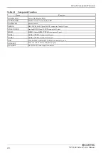
Page 25: ...SW Power switch SERIAL RS 232C 422 485 9pin D SUB connector male 1 port ANALOG RGB Analog RGB 15pin D SUB connector 1 port HDMI HDMI 19pin HDMI TYPE A connector 1 port USB3 0 USB3 0 TYPE A connector 1...

Page 26: ...D in front of this product Table 4 2 Display Contents of LED LED name Status Display contents POWER LED OFF Indicates that this product is switched off ON Blue Indicates that this product is switched...

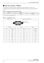
Page 27: ...buffer Table 4 3 SERIAL I O Addresses and Interrupts SERIAL I O Address Interrupt 3F8h 1 IRQ 4 1 1 Leave these settings as configured Table 4 4 Serial Port Connector Connector type 9pin D SUB connecto...

Page 28: ...This is because the frequency and resolution of Windows and MS DOS full screen display are the same due to the screen settings while the display parameters are different For display as only one param...

Page 29: ...DDC DATA 17 GND 18 VCC 19 HDMI HPD IN If the OS is booted without connecting the display cable and then the display is connected after the OS boots the display may not be shown properly When using a...

Page 30: ...t connector Connector type TYPE A connector female Pin No Signal name 1 USB_VCC 2 DATA 3 DATA 4 USB_GND 5 SSRX 6 SSRX 7 USB_GND 8 SSTX 9 SSTX USB2 0 Port Interface USB2 0 The product is equipped with...

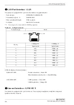
Page 31: ...le 4 9 LAN port connector Connector type RJ 45 Pin No 100Base TX 1000Base T Signal name Signal name 1 TX TRD 0 2 TX TRD 0 3 RX TRD 1 4 N C TRD 2 5 N C TRD 2 6 RX TRD 1 7 N C TRD 3 8 N C TRD 3 LEDs for...

Page 32: ...mation contained in the FLASH ROM and begins the process of checking out the system and configuring it When it finishes the BIOS will seek an operating system on one of the disks and then launch and t...

Page 33: ...F2 Key Load the previous settings F3 Key Load the optimal defaults from the BIOS default table F4 Key Save all the changed settings to the FLASH ROM and exit Getting Help Press F1 to pop up a small h...

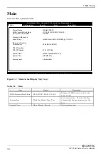
Page 34: ...Atom TM CPU E3845 1 91GHz Memory Information Total Memory 2048 MB LPDDR3 TXE Information TXE FW Version 01 01 00 1089 System Date Week Day MM DD YYYY System Time HH MM SS Access Level Administrator V...

Page 35: ...ormation Total Memory 2048 MB LPDDR3 TXE Information TXE FW Version 01 01 00 1089 System Date Week Day MM DD YYYY System Time HH MM SS Access Level Administrator Version x xx xxxx Copyright C 20xx Ame...

Page 36: ...2 Previous Values F3 Optimized Defaults F4 Save Exit ESC Exit Version x xx xxxx Copyright C 20xx American Megatrends Inc Figure 5 3 Configuration CPU Configuration Configure the CPU settings Chipset C...

Page 37: ...5 BIOS Setup 32 VPC 500 Series User s Manual H W Monitor View such hardware monitor information as the CPU temperature Serial Port Console Configuration Configure the Serial port console settings...

Page 38: ...1024 KB x 2 Active Processor Cores All Intel Virtualization Technology Enabled EIST Enabled CPU C6 report Disabled Select Screen Select Item Enter Select Change Opt F1 General Help F2 Previous Values...

Page 39: ...Total Memory 2048 MB LPDDR3 Select Screen Select Item Enter Select Change Opt F1 General Help F2 Previous Values F3 Optimized Defaults F4 Save Exit ESC Exit Version x xx xxxx Copyright C 20xx America...

Page 40: ...h Legacy PXE Rom Disable Wake On Lan Controller Enabled Select Screen Select Item Enter Select Change Opt F1 General Help F2 Previous Values F3 Optimized Defaults F4 Save Exit ESC Exit Version x xx xx...

Page 41: ...IGD Output Display control CSM Primary IGFX Boot Display CRT Secondary IGFX Boot Display HDMI Select Screen Select Item Enter Select Change Opt F1 General Help F2 Previous Values F3 Optimized Default...

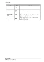
Page 42: ...Configure the settings for the port that will be output as the main display at start up If the main and auxiliary is connected only the main display is displayed during BIOS display and OS recovery Ca...

Page 43: ...Security Boot Save Exit PCI PCIE Configuration PCI Express Configuration Select Screen Select Item Enter Select Change Opt F1 General Help F2 Previous Values F3 Optimized Defaults F4 Save Exit ESC Ex...

Page 44: ...SC Exit Version x xx xxxx Copyright C 20xx American Megatrends Inc Figure 5 9 PCI Express Configuration Table 5 8 PCI Express Configuration Item Option Description PCI Express Port 0 Enabled Disabled...

Page 45: ...Version x xx xxxx Copyright C 20xx American Megatrends Inc Figure 5 10 SATA Configuration Table 5 9 SATA Configuration Item Option Description Serial ATA SATA Enabled Disabled Configure the SATA cont...

Page 46: ...Values F3 Optimized Defaults F4 Save Exit ESC Exit Version x xx xxxx Copyright C 20xx American Megatrends Inc Figure 5 11 USB Configuration Table 5 10 USB Configuration Item Option Description Legacy...

Page 47: ...ts F4 Save Exit ESC Exit Version x xx xxxx Copyright C 20xx American Megatrends Inc Figure 5 12 USB Configuration Table 5 11 USB Configuration Item Option Description USB OTG Support PCI mode Disabled...

Page 48: ...figuration Item Option Description Enable Hibernation Disabled Enabled Configure the hibernation settings ACPI Sleep State Suspend Disabled S3 Suspend to RAM Configure the sleep state settings Restore...

Page 49: ...tion Wake up Day 1 31 Sets the day the system will automatically turn on If 0 is set it is turned on a power supply every day Wake up Hour 0 23 Sets the time the system will automatically turn on Wake...

Page 50: ...ice Support Disabled Current Status Information No Security Device Found Select Screen Select Item Enter Select Change Opt F1 General Help F2 Previous Values F3 Optimized Defaults F4 Save Exit ESC Exi...

Page 51: ...t Item Enter Select Change Opt F1 General Help F2 Previous Values F3 Optimized Defaults F4 Save Exit ESC Exit Version x xx xxxx Copyright C 20xx American Megatrends Inc Figure 5 15 Super IO Configurat...

Page 52: ...41 C System temperature2 35 C Fan1 Speed N A Vcore 0 915 V 3 3V 3 277 V 5V 5 034 V 12V 12 421 V 1 35V 1 350 V Select Screen Select Item Enter Select Change Opt F1 General Help F2 Previous Values F3 Op...

Page 53: ...Disabled Console Redirection Port Is Disabled Console Redirection Disabled Select Screen Select Item Enter Select Change Opt F1 General Help F2 Previous Values F3 Optimized Defaults F4 Save Exit ESC E...

Page 54: ...elect Change Opt F1 General Help F2 Previous Values F3 Optimized Defaults F4 Save Exit ESC Exit Version x xx xxxx Copyright C 20xx American Megatrends Inc Figure 5 18 Security Administrator Password S...

Page 55: ...hange Opt F1 General Help F2 Previous Values F3 Optimized Defaults F4 Save Exit ESC Exit Version x xx xxxx Copyright C 20xx American Megatrends Inc Figure 5 19 Boot Table 5 18 Boot Item Option Descrip...

Page 56: ...SB removable drives 1 1 Appears when the device is connected In the Boot Option x device list the same device may be displayed as follows 1 USB Disk 2 UEFI USB Disk In such cases if 1 is selected a le...

Page 57: ...t Item Enter Select Change Opt F1 General Help F2 Previous Values F3 Optimized Defaults F4 Save Exit ESC Exit Version x xx xxxx Copyright C 20xx American Megatrends Inc Figure 5 20 Save Exit Save Chan...

Page 58: ...m primary battery Model CR2032 Maker MITSUBISHI Nominal voltage 3V Nominal capacity 220mAh Lithium content 1g or less Removing the battery Remove the battery according to the following figure Figure 6...

Page 59: ...awa ku Osaka 555 0025 Japan Japanese http www contec co jp English http www contec com Chinese http www contec com cn No part of this document may be copied or reproduced in any form by any means with...

Reviews: