


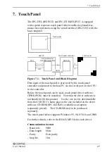


5. Installation Procedure
User’s Manual
17
5.
Installation Procedure
(1) Cut a panel in the following dimensions for installing the
display.
The four corners of the solid-line rectangle define the panel cut
dimensions. The holes (12) on dashed lines represent stud
holes.
119
119
119
344
98
98
98
28
1
12
φ
05
[mm]
Figure 5.1. Display Mounting Position
(IPC-DT/L40S(PC)T)
137
137
137
398
10
6
106
10
7
30
6
12
φ
05
[mm]
Figure 5.2. Display Mounting Position
(IPC-DT/H40X(PC)T)
Summary of Contents for IPC-DT/H40X(PC)T
Page 9: ...1 Introduction 6 User s Manual...
Page 13: ...2 Specifications 10 User s Manual...
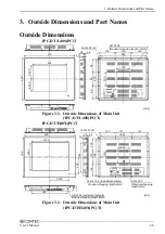
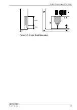
Page 16: ...3 Outside Dimensions and Part Names User s Manual 13 45mm 20mm Figure 3 5 Cable Bend Dimension...
Page 29: ...6 Connection to the Host Computer and Power Supply 26 User s Manual...
Page 31: ...7 Touch Panel 28 User s Manual...