


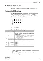


4. Setting the Display
16
User’s Manual
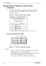
Specifications of Remote Control Cable
Connector
The display has the remote control cable connector on the back.
Given below are the pin assignments on the connector and an
example of using it.
Table 4.2. Remote Control Cable Connector
Pin No.
Signal name
*1 : The backlight remains off while the backlight ON/OFF signal has the GND level.
Brightness UP
GND
Brightness DOWN
Backlight ON/OFF *1
GND
GND
Cable connector (Side type)
S6B-XH-A(LF)(SN)(mfd. by JST)
Connector type
Model
1 2 3 4 5 6
1
2
3
4
5
6
Connector application example
1
2
3
4
5
6
SW1
SW2
SW3
Pushbutton switches (SW1, SW2)
ON/OFF switch (SW3)
Connector model: XHP-6 (JST)
Figure 4.2. Connector Application Example
Notes!
- Applying a GND-level voltage to the brightness UP or DOWN
signal increases or decreases the brightness.
- The brightness remains unchanged if the two signals (brightness
UP and DOWN signals) are input at the same time.
- The remote control cable is not bundled with this product.
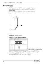
Summary of Contents for IPC-DT/H40X(PC)T
Page 9: ...1 Introduction 6 User s Manual...
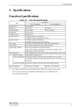
Page 13: ...2 Specifications 10 User s Manual...
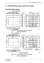
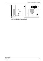
Page 16: ...3 Outside Dimensions and Part Names User s Manual 13 45mm 20mm Figure 3 5 Cable Bend Dimension...
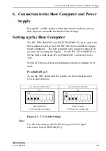
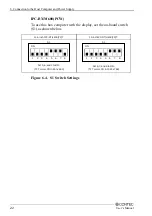
Page 29: ...6 Connection to the Host Computer and Power Supply 26 User s Manual...
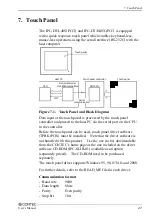
Page 31: ...7 Touch Panel 28 User s Manual...