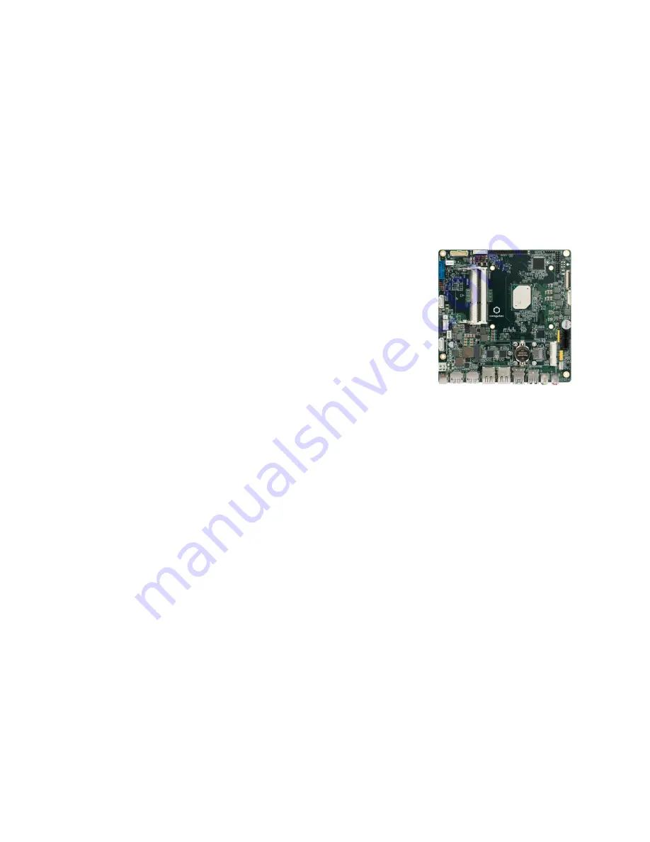
conga-IA5 Thin Mini-ITX SBC
Detailed Description Of The congatec Thin Mini-ITX Based On Intel® Apollo Lake SoCs
User's Guide
Revision 1.0
Page 1: ...conga IA5 Thin Mini ITX SBC Detailed Description Of The congatec Thin Mini ITX Based On Intel Apollo Lake SoCs User s Guide Revision 1 0...
Page 2: ...eaders Added caution about maximum cable length of USB 2 0 devices in section 5 5 1 USB 2 0 Ports 5 5 2 USB 3 0 Header and 5 5 3 USB 2 0 Header Added pinout description in section 5 5 2 USB 3 0 Header...
Page 3: ...the product and the user s guide In no event shall congatec AG be liable for any incidental consequential special or exemplary damages whether based on tort contract or otherwise arising out of or in...
Page 4: ...s call attention to important information that should be observed Connector Type Describes the connector used on the Single Board Computer Copyright Notice Copyright 2017 congatec AG All rights reserv...
Page 5: ...n specifications will be repaired or exchanged at congatec s option and expense Customer will obtain a Return Material Authorization RMA number from congatec AG prior to returning the non conforming p...
Page 6: ...com Terminology Term Description PCIe Peripheral Component Interface Express cBC congatec Board Controller SDIO Secure Digital Input Output USB Universal Serial Bus SATA Serial AT Attachment serial i...
Page 7: ...d S PDIF Header 27 5 2 5 Front Panel Audio Header 28 5 3 Communication Bus 29 5 3 1 SMBus 29 5 3 2 I C Bus 29 5 3 3 SPI Bus 29 5 4 LPC Interfaces 29 5 4 1 UART Headers 30 5 4 2 CPU and System Fan Head...
Page 8: ...6 5 4 OEM BIOS Code Data 53 6 5 5 OEM DXE Driver 53 6 6 congatec Battery Management Interface 53 6 7 API Support CGOS 54 6 8 Thermal Voltage Monitoring 54 6 9 Beeper 54 6 10 External System Wake Even...
Page 9: ...inout Description 26 Table 20 X21 Pinout Description 27 Table 21 X19 Pinout Description 27 Table 22 X18 Pinout Description 28 Table 23 X24 Pinout Description 30 Table 24 X25 Pinout Description 30 Tabl...
Page 10: ...TX boards are equipped with various interfaces such as PCI Express SATA USB 3 0 2 0 Ethernet Displays and Audio 1 2 conga IA5 The conga IA5 is a Single Board Computer design based on the Thin Mini ITX...
Page 11: ...he 2 MB 2 MB 2 MB 2 MB 2 MB Memory DDR3L 1866 MT s dual channel 1866 MT s dual channel 1866 MT s dual channel 1866 MT s dual channel 1866 MT s dual channel Processor Graphics Intel HD Graphics 505 Int...
Page 12: ...A female connector cab ThinMini ITX USB20 Twin 14000123 20cm USB 2 0 cable Twin with 2x5pin female header and two USB 2 0 Type A female connectors cab ThinMini ITX USB30 Twin 14000124 25cm USB 3 0 cab...
Page 13: ...ck Onboard I O Connectors 1x ATX 4 Pin Connector 1x SBM3 Connectors optional 1x CR2032 Cell Battery Holder 1x Stereo Speakers Header 1x Digital Microphone and S PDIF Header 1x Front Panel Audio Header...
Page 14: ...available on your particular module 2 2 Supported Operating Systems The conga IA5 supports the following operating systems Microsoft Windows 10 IoT Enterprise 64 bit Microsoft Windows 10 IoT Core 32...
Page 15: ...te maximum rating of the input voltage is 36 volts Do not exceed this rating or expose the conga IA5 to the absolute maximum voltage for a prolonged time Doing so may damage the system or affect syste...
Page 16: ...sconnected before measurement Table 9 Power Consumption Values The tables below provide additional information about the power consumption data for each of the conga IA5 variants offered The values ar...
Page 17: ...ime of the CMOS battery For more information refer to application note AN9_RTC_Battery_Lifetime pdf on congatec AG website at www congatec com support application notes We recommend to always have a C...
Page 18: ...USB3 0 SPI SD3 MIPI eDP LVDS eDP DDI1 DP DDI0 2x USB 2 0 USB2 0 2x USB 3 0 USB3 0 SATA0 RTC PCIe2 PCIe2 PCIe 2 SATA1 USB3 0 default or PCIe5 requires custom BIOS USB2 0 PCIe4 USB2 0 Front Panel Micro...
Page 19: ...ide sufficient air flow to each of the components to ensure the specified operating temperature of the conga IA5 is maintained congatec AG offers the following cooling options for the conga IA5 A cong...
Page 20: ...he other screws in a crossover pattern All the while keep holding the cooling adapter straight with one hand Now you can fully tighten the screws Once again start with one and then continue to tighten...
Page 21: ...s Celeron and Pentium Lidless Die Variants PN 052830 19 75 21 2 75 75 Note All measurements are in millimeters Recommended maximum torque for cooling solution screws is 0 3 Nm Mechanical system assemb...
Page 22: ...Atom Lidded Die Variants PN 052831 19 75 21 2 75 75 Note All measurements are in millimeters Recommended maximum torque for cooling solution screws is 0 3 Nm Mechanical system assembly mounting shall...
Page 23: ...on 2 4 Supply Voltage Power Table 11 X43 Pinout Description Pin Function Inner Shell 12 24V Outer Shell GND Connector Type X43 DC power jack 7 4x5 1mm Singatron 2DC1003 000111 5 1 2 ATX 4 Pin Connecto...
Page 24: ...3 X45 X46 Connect the data control cable to header X45 Connect the power cable to connector X46 The supported power supply is defined in section 2 4 Supply Voltage Power Table 14 X45 Pinout Descriptio...
Page 25: ...Table 16 Power Status LEDs Description LED State Description ACPI State Off Power off S5 Steady Green Running S0 Steady Yellow Sleeping S3 5 1 6 CR2032 Cell Battery Holder The conga IA5 provides a CR2...
Page 26: ...D Analog ground 3 MIC1_R 1st Stereo microphone analog input right channel 4 A_GND Analog ground 5 SENSE_A Jack detect pin 1 6 A_GND Analog ground Connector Type X20 6 position 3 5mm single audio jack...
Page 27: ...UTR Right channel negative differential output Connector Type X21 4x1 pins 2 00mm pitch Pinrex 721 81 04TW00 5 2 4 Digital Microphone and S PDIF Header The conga IA5 provides a digital microphone DMIC...
Page 28: ...C2_R 2nd Analog stereo microphone input right channel 4 PRESENCE Active low signal that indicates that an Intel HD Audio dongle is connected to the analog header 5 LINE2_R 2nd Analog line input right...
Page 29: ...5 including the feature connector X35 described in section 6 11 of this document 5 3 3 SPI Bus The SPI signals are connected to the onboard SPI flash and also to the feature connector X35 The SPI sign...
Page 30: ...y 5 GND Ground 6 DSR Data Set Ready 7 RTS Request to Send 8 CTS Clear to Send 9 RI Ring Indicator 10 N C Not connected Table 24 X25 Pinout Description Pin Signal Description Pin Signal Description 1 N...
Page 31: ...ion Pin Signal 1 GND 2 VCC 5VDC 12VDC 3 FAN_TACHOIN 4 FAN_CTRL Table 27 X34 X37 Pinout Description Pin Configuration 1 2 FAN 12VDC default 2 3 FAN 5VDC Connector Type X36 X38 4x1 pins 2 54mm pitch fri...
Page 32: ...r X16 2x USB 3 0 2 0 Rear Ports Connector X17 1x USB 3 0 2 0 Internal Port Connector X14 USB 3 0 Port 0 USB 2 0 Signals USB 2 0 Signals SuperSpeed Signals SuperSpeed Signals SuperSpeed Signals USB 3 0...
Page 33: ...USB 2 0 device connected to any port shall not exceed 3 meters in order to comply to EN 55024 2010 5 5 2 USB 3 0 Header The conga IA5 provides one USB 3 0 header X14 with support for OTG Table 28 X12...
Page 34: ...d to this header shall not exceed 3 meters in order to comply to EN 55024 2010 5 5 3 USB 2 0 Header The conga IA5 offers one USB 2 0 header X15 Table 29 X15 Pinout Description Pin Signal 1 5V 2 D 3 D...
Page 35: ...5 connector with gigabit magnetic and LEDs Note Connectors X6 and X7 do not support the Intel AMT feature 5 7 SATA Connectors 5 7 1 SATA Power Connector The conga IA5 provides a SATA power connector X...
Page 36: ...lit when there is activity on CN1 or CN2 Connector Type CN1 CN2 Standard SATA connector Caution Do not connect a SATA device to CN1 if the SATA Power feature in the BIOS configuration is set to SATADO...
Page 37: ...the BIOS setup Table 31 X12 Pinout Description Pin Signal Pin Signal 1 CONFIG_3 2 3 3V 3 GND 4 3 3V 5 GND 6 FULL_CARD_PWROFF 7 USB_D 8 W_DISABLE_1 9 USB_D 10 LED1 optional 11 GND 12 Key 13 Key 14 15 1...
Page 38: ...C 59 N C 60 N C 61 N C 62 N C 63 N C 64 N C 65 N C 66 N C 67 RESET 68 SUSCLK 69 CONFIG_1 70 3 3V 71 GND 72 3 3V 73 GND 74 3 3V 75 CONFIG_2 Connector Type X12 M 2 type B slot compatible with card size...
Page 39: ...supports three simultaneous displays two DP and an LVDS or eDP displays 5 8 1 DP Ports The conga IA5 SBC provides two DP ports X26 X27 supporting DP HDMI and DVI displays Connector Type X26 X27 Dual D...
Page 40: ...5 LVDS_A3 6 LVDS_B3 7 GND 8 GND 9 LVDS_A2 10 LVDS_B2 11 LVDS_A2 12 LVDS_B2 13 GND 14 GND 15 LVDS_A1 16 LVDS_B1 17 LVDS_A1 18 LVDS_B1 19 GND 20 GND 21 LVDS_A0 22 LVDS_B0 23 LVDS_A0 24 LVDS_B0 25 GND 26...
Page 41: ...26 GND 7 eDP_TX2 27 eDP_HPD 8 GND 28 GND 9 eDP_TX1 29 GND 10 eDP_TX1 30 GND 11 GND 31 GND 12 eDP_TX0 32 eDP_LVDS_BKLT_EN 13 eDP_TX0 33 eDP_LVDS_BKLT_CTRL 14 GND 34 N C 15 eDP_AUX 35 N C 16 eDP_AUX 36...
Page 42: ...S_BKLT_CTRL Backlight control 3 BKLT_PWR Backlight inverter power 4 BKLT_PWR Backlight inverter power 5 GND Backlight brightness ground 6 GND Backlight brightness ground 7 Brightness_Up Flat panel bri...
Page 43: ...can set the panel voltage to 3 3V 5V or 12V Table 35 X31 Pinout Description Pin Signal Name 1 No Pin 2 N C 3 12V 4 Selected backlight power 5 No Pin 6 5V Table 36 X30 Pinout Description Pin Signal Na...
Page 44: ...Ie full size card slot You can use either the mini PCIe half size or full size card slot 5 9 1 PCIe x1 Card Slot The conga IA5 provides one PCIe x1 card slot X8 This connector shares the SoC s PCIe 2...
Page 45: ...x1 Card Slot Note You can use either the PCIe x1 X8 or mPCIe slot X9 The PCIe x1 slot x8 will not function if you insert a card into the mPCIe slot X9 5 9 2 Mini PCIe Card Slot Half Size The conga IA5...
Page 46: ...x 25 PERp0 26 GND 27 GND 28 1 5V 29 GND 30 SMB_CLK 31 PETn0 32 SMB_DATA 33 PETp0 34 GND 35 GND 36 USB_D 37 GND 38 USB_D 39 3 3Vaux 40 GND 41 3 3Vaux 42 N C 43 mSATA_mPCIe_detect 44 N C 45 CL_CLK 46 N...
Page 47: ...X9 the SoC automatically detects the type of device that is attached via pin 43 the signal detect pin See section 5 10 2 Mini PCIe Half Size for the mini PCIe Pinout Description Connector Type X9 Mini...
Page 48: ...ion Pin Signal Description C1 PWR Power C2 RST Reset C3 CLK Clock C4 N A Not available C5 GND Ground C6 VPP Programming voltage input C7 I O Data C8 N A Not available Connector Type X10 Micro SIM Card...
Page 49: ...an be connected to the M 2 slot X12 It is connected to the mPCIe slot X9 by default You can have either USB3 0 default or PCIe5 signals on the M 2 slot X12 You can change the signals to PCIe5 with a c...
Page 50: ...wer LED main color 3 SATA_ACT Hard disk activity LED 4 FP_LED Power LED alternate color 5 GND Ground 6 PWRBTN Power button 7 SYS_RST Reset button 8 GND Ground 9 3 3V 3 3V power supply 500mA power budg...
Page 51: ...e embedded features such as system monitoring or the I C bus from the x86 core architecture which results in higher embedded feature performance and more reliability even when the x86 processor is in...
Page 52: ...ult Settings This feature allows system designers to create and store their own BIOS default configuration Customized BIOS development by congatec for OEM default settings is no longer necessary becau...
Page 53: ...e the development of battery powered mobile systems based on embedded modules congatec AG has defined an interface for the exchange of data between a CPU module using an ACPI operating system and a Sm...
Page 54: ...modified on all congatec CPU modules All the hardware related code is contained within the congatec embedded BIOS on the module See section 1 1 of the CGOS API software developers guide which is avail...
Page 55: ...ut 3 3V standby PU 2k SMBus Alert system wake or SMI active low 14 GND Ground 15 TX_FEAT Output 3 3V UART port from SoC TX assembly option UART from Board controller 16 RX_FEAT Input 3 3V UART port fr...
Page 56: ...3V standby PU 100k external Thermal event active low 39 WDOUT Output 3 3V PD 10k Watchdog event output Board controller event after timer expires 40 WDTRIG_IN Input 3 3V PU 10k Watchdog trigger input...
Page 57: ...50m10 57 59 7 conga IA5 Mechanical Drawing 170 170 X43 X44 X48 X26 X27 X6 X7 X17 X16 X22 X20 X21 X18 X8 X19 M18 X2 X1 X42 X25 X24 X15 X35 X32 X30 X31 X33 X36 X14 X34 X23 X39 CN1 X28 X47 X11 X37 X45 CN...
Page 58: ...ied as IA50R1xx where IA5 is the project name R is the identifier for a BIOS ROM file 1 is the feature number xx is the major and minor revision number The binary size of conga IA5 BIOS is 8MB 8 3 Upd...
Page 59: ...eveloper intel com design chipsets industry lpc htm Universal Serial Bus USB Specification Revision 2 0 http www usb org home PCI Specification Revision 2 3 http www pcisig com specifications Serial A...