background image

Copyright 

© 

2022 

congatec 

GmbH 


      TCTOm01 


15/70

2.4 

Supply Voltage Standard Power


8 V – 20 V DC 

2.4.1 

Electrical Characteristics

Power supply pins on the module’s connectors limit the amount of input power. The following table provides an overview of the limitations for 
pinout Type 6 (dual connector, 440 pins).

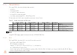
Table 5  

Overview of Type 6 Limitations

Power Rail Module Pin 

Current Capability 

(Ampere)

Nominal 

Input (Volts)

Input 

Range 

(Volts)

Derated 

Input (Volts)

Max. Input Ripple 

(10Hz to 20MHz)

(mV)

Max. Module Input 

Power (w. derated input)

(Watts)

Assumed 

Conversion 

Efficiency

Max. Load 

Power

(Watts)

VCC_12V

12

12

11.4-12.6 11.4

+/- 100

137

85%

116

VCC_5V-SBY

2

5

4.75-5.25 4.75

+/- 50

9

VCC_RTC

0.5

3

2.5-3.3

+/- 20

2.4.2 

Rise Time

The input voltages shall rise from 10 percent of nominal to 90 percent of nominal at a minimum slope of 250 V/s. The smooth turn-on requires 
that, during the 10 percent to 90 percent portion of the rise time, the slope of the turn-on waveform must be positive.

2.5 

Power Consumption

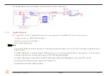
The power consumption values were measured with the following setup:


Input v12 V


conga-TC570r COM


Modified congatec carrier board


conga-TC570r cooling solution


Microsoft Windows 10 (64 bit)


Note

The CPU was stressed to its maximum workload with the Intel

®

 Thermal Analysis Tool

Summary of Contents for COM Express conga-TC570r

Page 1: ...COM Express conga TC570r 11th Generation Intel Core i7 i5 i3 and Celeron Single Chip UP3 Processors Soldered Down Memory User s Guide Revision 0 1 Preliminary...

Page 2: ...Copyright 2022 congatec GmbH TCTOm01 2 70 Revision History Revision Date yyyy mm dd Author Changes 0 1 2022 03 15 AEM Preliminary release...

Page 3: ...ongatec com en licenses Search for the revision of the BIOS UEFI or Board Controller Software as shown in the POST screen or BIOS setup to get the complete product related license information To the e...

Page 4: ...ntract or otherwise arising out of or in connection with this user s guide or any other information contained herein or the use thereof Intended Audience This user s guide is intended for technically...

Page 5: ...ec GmbH All rights reserved All text pictures and graphics are protected by copyrights No copying is permitted without written permission from congatec GmbH congatec GmbH has made every attempt to ens...

Page 6: ...e non conforming product freight prepaid congatec GmbH will pay for transporting the repaired or exchanged product to the customer Repaired replaced or exchanged product will be warranted for the repa...

Page 7: ...t you If you still require assistance after visiting our website then contact our technical support department by email at support congatec com Terminology Term Description EU Execution Unit GB Gigaby...

Page 8: ...1 4 SATA 27 5 1 5 USB 27 5 1 6 Gigabit Ethernet 28 5 1 7 High Definition Audio 29 5 1 8 LPC Bus 29 5 1 9 I C Bus 29 5 1 10 GPIOs 29 5 1 11 General Purpose Serial Interface 29 5 1 12 Power Control 30 5...

Page 9: ...or Signal Descriptions 43 8 2 Bootstrap Signals 65 9 System Resources 66 9 1 I O Address Assignment 66 9 1 1 LPC Bus 66 9 2 PCI Configuration Space Map 67 9 3 I2 C 68 9 4 SM Bus 68 10 BIOS Setup Descr...

Page 10: ...ayPort DP Signal Descriptions 53 Table 20 Embedded DisplayPort Signal Descriptions 54 Table 21 CRT Signal Descriptions 55 Table 22 LVDS Signal Descriptions 55 Table 23 Serial ATA Signal Descriptions 5...

Page 11: ...are legacy free design no Super I O PS 2 keyboard and mouse and provide most of the functional requirements for any application These functions include but are not limited to a rich complement of cont...

Page 12: ...Carrier Board for COM Express Type 6 modules Table 3 conga TC570r Industrial Variants Part No 050330 050331 050312 Processor Intel Core i7 1185GRE 1 8 GHz Quad Core Intel Core i5 1145GRE 1 5 GHz Quad...

Page 13: ...hardware accelerated video decode encode processing transcode Up to four independent displays see table 10 Display Combination and Resolution 3x DP 1x LVDS eDP 2 1x PEG x4 port PCIe Gen 4 1x VGA 3 Re...

Page 14: ...osoft Windows 10 64 bit Microsoft Windows 10 IoT Enterprise 64 bit Linux Ubuntu 64 bit Real Time Systems Hypervisor Note 1 The processor supports only 64 bit operating systems 2 The conga TC570r suppo...

Page 15: ...umed Conversion Efficiency Max Load Power Watts VCC_12V 12 12 11 4 12 6 11 4 100 137 85 116 VCC_5V SBY 2 5 4 75 5 25 4 75 50 9 VCC_RTC 0 5 3 2 5 3 3 20 2 4 2 Rise Time The input voltages shall rise fr...

Page 16: ...C_5V_SBY S5 COM is powered by VCC_5V_SBY S5e COM is powered by VCC_5V_SBY Note 1 The fan and SATA drives were powered externally 2 All other peripherals except the LCD monitor were disconnected before...

Page 17: ...AN9_RTC_Battery_Lifetime pdf on congatec GmbH website at www congatec com support application notes 4 We recommend to always have a CMOS battery present when operating the conga TC570r 2 7 Environmen...

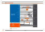
Page 18: ...00 2500 Intel i225LM V IT eDP to LVDS eSPI to LPC MUX MUX MUX MUX MUX DP to VGA MIPI CSI SATA0 PCIe6 SATA0 SATA0 SATA1 PCIe5 SATA1 SATA1 PCIe6 PCIe6 USB 3 2 Port 3 PCIe7 PCIe7 PCIe5 PCIe5 PCIe0 4 Opti...

Page 19: ...he environmental conditions it is subjected to For more information about this subject contact your local congatec sales representative and request the gap pad material manufacturer s specification Ca...

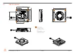
Page 20: ...yright 2022 congatec GmbH TCTOm01 20 70 4 1 CSA Dimensions M2 5 x 11 mm threaded standoff for threaded version or 2 7 x 11 mm non threaded standoff for borehole version 87 95 87 95 37 25 76 62 4 25 5...

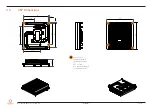
Page 21: ...ght 2022 congatec GmbH TCTOm01 21 70 4 2 CSP Dimensions M2 5 x 11 mm threaded standoff for threaded version or 2 7 x 11 mm non threaded standoff for borehole version 87 87 95 57 6 37 25 95 24 3 76 62...

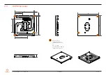
Page 22: ...ight 2022 congatec GmbH TCTOm01 22 70 4 3 HSP Dimensions M2 5 x 11 mm threaded standoff for threaded version or 2 7 x 11 mm non threaded standoff for borehole version 87 37 25 57 6 87 62 4 76 4 4 11 9...

Page 23: ...4 3 2 1 Heatspreader Thermal Imagery The conga TC570r heatspreader solution features heatstack heat pipe and aluminium alloy plate The aluminium alloy plate distributes the heat evenly on the heatspre...

Page 24: ...ports the following up to 8 GTps Gen 3 speed a 6x1 link default configuration with SATA ports enabled 1 2 3 a 1 x4 2 x1 link or 2 x2 2 x1 link or 1 x2 4 x1 link via a special customized BIOS firmware...

Page 25: ...36 bpp LVDS or eDP 1920x1200 60 Hz dual LVDS mode 4096x2304 60 Hz 24 bpp Option 2 DP 4096x2304 60 Hz 36 bpp DP 4096x2304 60 Hz 36 bpp DP 4096x2304 60 Hz 36 bpp VGA 1920x1200 60 Hz Option 3 DP 4096x230...

Page 26: ...ppings automatic panel detection via Embedded Panel Interface based on VESA EDIDTM 1 3 resolution up to 1920x1200 in dual LVDS channel mode The eDP 1 2 interface supports eDP 1 4 specification Spread...

Page 27: ...ification SuperSpeedPlus SuperSpeed High Speed Full Speed and Low Speed USB signaling data transfers of up to 10 Gbps for USB 3 2 Gen 2x1 port data transfers of up to 5 Gbps for USB 3 2 Gen 1x1 port s...

Page 28: ...te 1 The Intel i225 IT Ethernet controller supports 2 5 Gb mode at temperature range of 40 C to 70 C and 1 Gb mode at temperature range of 40 C to 85 C 2 The GBE0_LINK output is not active during a 10...

Page 29: ...and accessed through the congatec CGOS driver and API The controller provides a fast mode multi master I C bus that has the maximum I C bandwidth 5 1 10 GPIOs The conga TC570r offers General Purpose I...

Page 30: ...board hardware must drive this signal low until all power rails and clocks are stable Releasing PWR_OK too early or not driving it low at all can cause numerous boot up problems It is a good design p...

Page 31: ...y be only around 0 8 V when the 12 V is applied to the module Actively driving PWR_OK high is compliant to the COM Express specification but this can cause back driving Therefore congatec recommends d...

Page 32: ...OS settings or by system software Standard 12V Power Supply Implementation Guidelines The 12 volt input power is the sole operational power source for the conga TC570r Other required voltages are gene...

Page 33: ...n while in S3 S4 S5 In the Deep Sx state the system entry condition determines if the system context is maintained or not All power is shut off except for minimal logic which supports limited set of w...

Page 34: ...e following features 6 1 1 Board Information The cBC provides a rich data set of manufacturing and board information such as serial number EAN number hardware and firmware revisions and so on It also...

Page 35: ...erate the correct speed readout 2 For the correct fan control FAN_PWMOUT FAN_TACHIN implementation see the COM Express Design Guide 6 1 7 Enhanced Soft Off State The conga TC570r supports an enhanced...

Page 36: ...m utility CGUTIL 1 5 4 or later to replace add the OEM POST logo 6 2 4 OEM DXE Driver This feature allows designers to add their own UEFI DXE driver to the congatec embedded BIOS Contact congatec tech...

Page 37: ...ilable for all commonly used Operating Systems such as Win32 Win64 Win CE Linux The architecture of the CGOS API driver provides the ability to write application software that runs unmodified on all c...

Page 38: ...reduce frequency and voltage adaptively The Adaptive Thermal Monitor will remain active as long as the package temperature remains at its specified limit Therefore the Adaptive Thermal Monitor will co...

Page 39: ...d Collaborative Processor Performance Control CPPC2 and is supported by newer operating systems Win 8 1 or newer With this feature enabled the processor autonomously selects performance states based o...

Page 40: ...the virtualization performance and robustness RTS Real Time Hypervisor supports Intel VT and is verified on all current congatec x86 hardware Note congatec supports RTS Hypervisor 7 4 Thermal Manageme...

Page 41: ...tions Remarks Power Button Wakes unconditionally from S3 S5 Onboard LAN Event Device driver must be configured for Wake On LAN support SMBALERT Wakes unconditionally from S3 S5 PCI Express WAKE Wakes...

Page 42: ...sted For information about the internal pull ups or pull downs implemented by the chip vendors refer to the respective chip s datasheet Table 12 Signal Tables Terminology Descriptions Term Description...

Page 43: ...CIE_TX0 B68 PCIE_RX0 A14 GBE0_CTREF 1 B14 SMB_DAT A69 PCIE_TX0 B69 PCIE_RX0 A15 SUS_S3 B15 SMB_ALERT 3 A70 GND FIXED B70 GND FIXED A16 SATA0_TX B16 SATA1_TX A71 eDP_TX2 LVDS_A0 B71 LVDS_B0 A17 SATA0_T...

Page 44: ...B41 GND FIXED A96 TPM_PP B96 VGA_I2C_DAT A42 USB2 B42 USB3 A97 TYPE10 1 B97 SPI_CS A43 USB2 B43 USB3 A98 SER0_TX B98 RSVD 1 A44 USB_2_3_OC B44 USB_0_1_OC A99 SER0_RX B99 RSVD 1 A45 USB0 B45 USB1 A100...

Page 45: ...G_RX5 1 D69 PEG_TX5 1 C15 DDI1_PAIR6 1 D15 DDI1_CTRLCLK_AUX C70 GND FIXED D70 GND FIXED C16 DDI1_PAIR6 1 D16 DDI1_CTRLDATA_AUX 3 C71 PEG_RX6 1 D71 PEG_TX6 1 C17 RSVD D17 RSVD C72 PEG_RX6 1 D72 PEG_TX6...

Page 46: ...ND C42 DDI3_PAIR1 D42 DDI2_PAIR1 C97 RVSD 1 D97 RSVD 1 C43 DDI3_PAIR1 D43 DDI2_PAIR1 C98 PEG_RX14 1 D98 PEG_TX14 1 C44 DDI3_HPD D44 DDI2_HPD C99 PEG_RX14 1 D99 PEG_TX14 1 C45 RSVD 1 D45 RSVD 1 C100 GN...

Page 47: ...PCIE_TX4 A55 A56 PCI Express channel 4 Transmit Output differential pair O PCIE PCIE_RX5 PCIE_RX5 B52 B53 PCI Express channel 5 Receive Input differential pair I PCIE Shared with SATA port 1 and conf...

Page 48: ...O PCIE PEG_RX4 PEG_RX4 C65 C66 PCI Express Graphics differential pairs 4 Note Can also be used as PCI Express differential pairs 20 I PCIE Not connected PEG_TX4 PEG_TX4 D65 D66 O PCIE PEG_RX5 PEG_RX5...

Page 49: ...rential pairs 28 I PCIE PEG_TX12 PEG_TX12 D91 D92 O PCIE PEG_RX13 PEG_RX13 C94 C95 PCI Express Graphics differential pairs 13 Note Can also be used as PCI Express differential pairs 29 I PCIE PEG_TX13...

Page 50: ...TA if DDI1_DDC_AUX_SEL is pulled high I O PCIE I O OD 3 3 V PU 100 k 3 3V Bootstrap signal see note below DDI enable strap is already populated DDI1_DDC_AUX_SEL D34 Selects the function of DDI1_CTRLCL...

Page 51: ...PCIE I O OD 3 3 V PD 100 k DDI3_CTRLDATA_AUX 1 C37 Multiplexed with DP3_AUX and HDMI3_CTRLDATA DP AUX function if DDI3_DDC_AUX_SEL is no connect HDMI DVI I2C CTRLDATA if DDI3_DDC_AUX_SEL is pulled hi...

Page 52: ...with DDI2_CTRLCLK_AUX I O OD 3 3 V PD 100 k HDM12_CTRLDATA 1 C33 TMDS I2 C Control Data Multiplexed with DDI2_CTRLDATA_AUX I O OD 3 3 V PU 100 k 3 3 V Bootstrap signal see note below Enable strap is a...

Page 53: ...100 k 3 3 V Bootstrap signal see note below DP enable strap is already populated DP2_LANE3 DP2_LANE3 D49 D50 Uni directional main link for the transport of isochronous streams and secondary data Mult...

Page 54: ...and EDID access I O PCIE PD 100 k DP3_AUX 1 C37 Half duplex bi directional AUX channel for services such as link configuration or maintenance and EDID access I O PCIE PU 100 k 3 3 V Bootstrap signal s...

Page 55: ...face on industrial variants you need a customized conga TC570r variant assembly option Table 22 LVDS Signal Descriptions Signal Pin Description I O PU PD Comment LVDS_A0 LVDS_A0 LVDS_A1 LVDS_A1 LVDS_A...

Page 56: ...tial pair O SATA SATA3_RX SATA3_RX B25 B26 Serial ATA channel 3 receive input differential pair I SATA Not connected SATA3_TX SATA3_TX B22 B23 Serial ATA channel 3 transmit output differential pair O...

Page 57: ...carrier board USB0_HOST_ PRSNT B48 Module USB client may detect the presence of a USB host on USB0 A high values indicates that a host is present I 3 3 VSB PD 1 M Not Supported Note 1 These signals ha...

Page 58: ...GBE0_LINK1000 2 A5 Gigabit Ethernet Controller 0 1000 Mbps link indicator active low OD 3 3 V GBE0_CTREF A14 Reference voltage for Carrier Board Ethernet channel 0 magnetics center tap The reference...

Page 59: ...gnal Pin Description I O PU PD Comment LPC_AD 0 3 B4 B7 LPC Mode LPC multiplexed address command and data bus I O 3 3 V PU 20 K 3 3 V LPC_FRAME B3 LPC Mode LPC Frame indicates the start of a LPC cycle...

Page 60: ...ring the reset process They may bootstrap some basic important functions of the module For more information refer to section 8 2 Bootstrap Signals Table 30 Miscellaneous Signal Descriptions Signal Pin...

Page 61: ...ides GPIO signals on the COM Express connector by default Table 32 Power and System Management Signal Descriptions Signal Pin Description I O PU PD Comment PWRBTN B12 Power button to bring system out...

Page 62: ...P B103 Sleep button Used by the ACPI operating system to bring the system to sleep state or to wake it up again Note For proper detection assert a pulse width of at least 16 ms I OD 3 3 V PU 100 k 3 3...

Page 63: ...r logic level Table 37 Module Type Definition Signal Description Signal Pin Description I O Comment TYPE0 TYPE1 TYPE2 C54 C57 D57 The TYPE pins indicate to the carrier board the pinout type that is im...

Page 64: ...criptions Signal Pin Description I O PU PD Comment VCC_12V A104 A109 B104 B109 C104 C109 D104 D109 Primary power input 12V nominal All available VCC_12V pins on the connector s shall be used P VCC_5V_...

Page 65: ...if DDI1_DDC_AUX_SEL is pulled high I O OD 3 3 V DDI2_CTRLDATA_AUX C33 Multiplexed with DP2_AUX and HDMI2_CTRLDATA PU 100 k 3 3 V DP2_AUX DP AUX function if DDI2_DDC_AUX_SEL is no connect I O PCIE HDMI...

Page 66: ...ecoded are forwarded to the PCI Bus not the ESPI or LPC Bus Only specified I O ranges are forwarded to the ESPI LPC Bus In the congatec Embedded BIOS the following I O address ranges are sent to the E...

Page 67: ...17h 00h SATA Controller 00h 1Ch 00h Not connected PCI Express Root Port 00h Note2 1Ch 04h PCI Express Root Port 5 00h Note2 1Ch 05h PCI Express Root Port 6 00h Note2 1Ch 06h PCI Express Root Port 7 00...

Page 68: ...if a device is attached to the PCI Express Slot on the carrier board 3 The Table represents a case when a Single function PCI PCIe device is connected to all possible slots on the carrier board The gi...

Page 69: ...u do not have access to the restricted area of the congatec website contact your local congatec sales representative 10 1 Navigating the BIOS Setup Menu The BIOS setup menu shows the features and opti...

Page 70: ...t www congatec com Note 1 Deprecated Caution The DOS command line tool is not officially supported by congatec and therefore not recommended for critical tasks such as firmware updates We recommend to...

Reviews: