


Copyright
©
2022
congatec
GmbH
TSTLm01
62/72
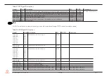
Table 26 Gigabit Ethernet Signal Descriptions
Gigabit Ethernet Pin # Description
I/O
PU/PD Comment
GB
GBE0_MDI0-
GB
GBE0_MDI1-
GB
GBE0_MDI2-
GB
GBE0_MDI3-
A13
A12
A10
A9
A7
A6
A3
A2
Gigabit Ethernet Controller 0: Media Dependent Interface Differential Pairs 0, 1, 2, 3.
The MDI can operate in 1000, 100, and 10 Mbps modes. Some pairs are unused in some
modes according to the following:
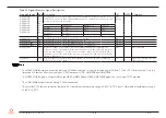
I/O
Analog
1000BASE-T
100BASE-TX
10BASE-T
MDI[0]+/-
B1_DA+/-
TX+/-
TX+/-
MDI[1]+/-
B1_DB+/-
RX+/-
RX+/-
MDI[2]+/-
B1_DC+/-
MDI[3]+/-
B1_DD+/-
GBE0_ACT#
B2
Gigabit Ethernet Controller 0 activity indicator, active low
OD 3.3 V
GBE0_LINK#
1, 2
A8
Gigabit Ethernet Controller 0 link indicator, active low
OD 3.3 V
GBE0_LINK100#
2
A4
Gigabit Ethernet Controller 0 100 Mbps link indicator, active low
OD 3.3 V
GBE0_LINK1000#
2,3
A5
Gigabit Ethernet Controller 0 1000 Mbps link indicator, active low
OD 3.3 V
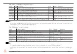
GBE0_CTREF
A14
Reference voltage for Carrier Board Ethernet channel 0 magnetics center tap. The
reference voltage is determined by the requirements of the module PHY and may be as
low as 0 V and as high as 3.3 V. The reference voltage output shall be current limited on
the module. In the case in which the reference is shorted to ground, the current shall be
limited to 250 mA or less
REF
Not connected
GBE0_SDP
A49
Gigabit Ethernet Controller 0 Software-Definable Pin. Can also be used for IEEE1588
support such as a 1 pps signal
I/O
Signal is provided by the Intel
i225 controller
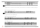
Note
1.
The GBE0_LINK# output is not active during a 10 Mb connection. It is only active during a 100 Mb, 1 Gb or 2.5 Gb connection. This is a
limitation of Ethernet Phy since it only has 3 LED outputs—ACT#, LINK100# and LINK1000#.
2.
The GBE0_LINK# signal is a logic AND of the GBE0_LINK100# and GBE0_LINK1000# signals on the conga-TS570 module.
3.
The LINK1000# output is active during 2.5 Gb connection
.
4.
The Intel i225-IT Ethernet controller supports 2.5 Gb mode at temperature range of -40
°
C to 70
°
C and 1 Gb mode at temperature range
of -40
°
C to 85
°
C


