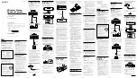


2.2 INSTALLATION PROCESS
1.
Site the Smoke Screen, fix to the wall or ceiling as appropriate.
2. Select the “Service Mode”dip switch to “On”.
3. Make connections as required to the alarm panel and hold-off PIR.
4. Make connection to the Smoke Screen Interface (if used) and set the key switch to isolate.
5. Connect and turn on the mains power.
6. Turn on the internal battery back-up.
7. The Smoke Screen will heat up to operating temperature in approximately 20 minutes.
8. Set correct time/date and smoke timing for the specified room size.
9. Ensure the “Service Mode” dip switch is selected to “Off”.
10. With the power applied insert fluid consumable and make sure the fluid switch is closed correctly.
11. Make sure all tamper switches are closed.
12. If fitted set the Smoke Screen Interface key switch to ‘Ready’ and you are ready for test.
2.3 ACCESS
To access the PCB connections, programming panel, mounting holes, batteries and fluid, remove the front cover by
unscrewing the 2 set screws on either side and unhooking it from the back plate; refitting is the reverse process.
Installation cable entry is through the serrated grommet on the right-hand side of the back plate.
9
Summary of Contents for SENTINEL S35
Page 1: ...1...
Page 15: ...Connections 4 4 1 CIRCUIT BOARD LAYOUT PCB v2 15...
Page 16: ...4 2 GENERIC CONNECTION DIAGRAM 16...
Page 29: ...8 2 INSTALLER NOTES 29...
Page 30: ...30...