background image


38 

7.3.2 Delete 

Virtual 

Server 

To delete a virtual server entry, follow the steps below. 
Step 1 

Enter the 

MAIN/CONF/NAT/SERVER/DELETE

 menu. 

Step 2 

Enter the following parameters of the virtual server. 


Protocol

: TCP and UDP (factory default: TCP) 


Interface

: LAN, and ATM1 to ATM16.  If the virtual

server is located at the same LAN interface as the CT-510,
select 

LAN

.  If the virtual server is located at the same

ADSL interface as the CT-510, select one of ATM1 to
ATM16.


Service Port Number: 

related to the service name. For

example, Web with port number 80. 

Step 3 

Hold down the Ctrl-S keys to delete the virtual server. 

7.3.3 

List Virtual Server Entry 

To display the virtual server entry, enter the 

MAIN/CONF/NAT/SERVER/LIST 

menu. 

7.4 

Configure NAT/PAT IP Pools 

This section specifies how to configure the CT-510 to do one-to-one, 

virtual-to-global IP address translation.   
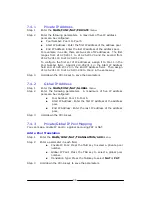
Step 1 

Assign the private IP addresses.    Refer to Section 7.4.1. 

Step 2 

Assign the global IP addresses.    The CT-510 allows up to five sets of
continuous global IP addresses.  The workstations in the private IP

pools will be translated to one of the global IP addresses that is set
in Section 7.4.2. 

Step 3 

Map the private IP pool to the global IP pool for NAT/PAT
functionality. Refer to Section 7.4.3. 

Step 4 

Assign the fixed IP address.  Refer to Section 7.4.4. 

Step 5 

Write the configurations in the flash memory by entering the

MAIN/WRITE

 menu. 

Step 6 

Reboot the system by entering the 

MAIN/REBOOT

 menu. 


Summary of Contents for CT-510

Page 1: ...CT 510 ADSL Router User Manual Version A3 0 June 3 2003 261028 002...

Page 2: ...duct updates new product releases manual revisions software upgrades and technical support visit Comtrend Corporation at http www comtrend com tw Copyright Copyright 2000 Comtrend Corporation All righ...

Page 3: ...13 CHAPTER 3 MANAGEMENT 14 3 1 Getting Started 14 3 2 How to access CT 510 15 3 2 1 Console 15 3 2 2 Telnet 16 3 2 3 Web 18 3 3 General Configuration Steps in Console Telnet 19 3 3 1 Configuration Ste...

Page 4: ...1 Overview 31 5 2 Static Bridging Configuration 31 5 2 1 Add A Static MAC Entry 31 5 2 2 Delete a Static MAC Address 32 5 2 3 List Static Bridging Parameters 32 5 3 Spanning Tree Protocol 32 5 4 Forw...

Page 5: ...T PAT Pool Translation 40 List NAT PAT Pool Translation 40 7 4 4 Fixed NAT IP Mapping 40 Add a Fixed IP Address Mapping 40 Delete a Fixed IP Address Mapping 40 List Fixed IP Mappings 40 CHAPTER 8 DNS...

Page 6: ...e 48 11 8 Performance Monitoring 49 11 8 1 ADSL Status Monitor 49 11 8 2 ATM Interface Monitor 50 11 8 3 ADSL Performance Statistics 50 11 8 4 Interface Performance Monitor 51 CHAPTER 12 WEB CONFIGURA...

Page 7: ...on via Web 1 1 Overview The CT 510 ADSL router uses the ADI chipset to satisfy the needs of multiple users for small office home office and remote office branch office applications The router has an i...

Page 8: ...VBR ATM services VC based and LLC multiplexing Up to 16 VCs 4 port 10BaseT Ethernet hub half duplex One console port for local management Embedded SNMP agent and ADSL Forum TR 006 ADSL Line MIB Web ba...

Page 9: ...wing diagrams a possible application of CT 510 It can be used for G lite and G DMT applications Figure 1 1 Application of CT 510 ANSI T1 413 ADSL ADSL G lite POTS splitter shelf ATM PSTN Micro filter...

Page 10: ...L Yellow Off No collision is detected On The physical connection between Ethernet port 1x 2x 3x or 4x and LAN device is established Off Ethernet connection is not made 1X 4X Green Flash Receive data O...

Page 11: ...75 Note 2 The HIGH MID and LOW LEDs are OFF when no downstream data is received 2 1 1 Rear Panel Connectors There are seven connectors on the rear panel To make a connection using these connectors pl...

Page 12: ...d Pin Definition Pin Definition 1 6 2 TD 7 3 RD 8 4 9 5 GND Table 2 1 Pin Assignments of Console Port An AC power adapter cord to connect to the Power jack A 110 VAC to 12 VAC or 220 VAC to 12 VAC pow...

Page 13: ...the pin assignments of the RJ11 connector Pin Definition Pin Definition 1 4 ADSL_TIP 2 5 3 ADSL_RING 6 Table 2 3 Pin Assignments of RJ11 Port Optional POTS splitter for G DMT and ANSI T1 413 features...

Page 14: ...with a power adapter cord Step 2 Connect any of the Ethernet ports 1x 4x to the LAN with RJ45 connector cables Up to four Ethernet ports can be connected Step 3 Connect the Console port to a VT 100 co...

Page 15: ...is provided that the user can enable or disable this function When set to Enabled a password will be required to access the console The default value of this function is disabled For more details plea...

Page 16: ...s follows Baud rate 9600 Parity none Data bits 8 Stop bit 1 Flow control none Step 2 Initially the console password check function is disabled therefore you will not be prompted to enter a password Af...

Page 17: ...main menu and select REBOOT to reboot the system Step 16 In less than one minute the sentence Press ESC key to enter console mode configuration displays Note 1 If you use HyperTerminal for the VT 100...

Page 18: ...USER type user in the Login field If the default password was changed type the password that was set in the console session refer to Section 3 1 1 Steps 9 13 If the default password was not changed ty...

Page 19: ...the default password was not changed type the password that was set in the console session refer to Section 3 1 1 Steps 9 13 If the default password was not changed type root To have read only access...

Page 20: ...to configure the LAN interface of the CT 510 please complete the following procedures Step 1 Enter the main menu The path prompts MAIN to indicate the directory of the current operating menu Step 2 Us...

Page 21: ...lash memory Refer to Section 11 2 for details Step 6 Reboot the system by entering the REBOOT menu from the main menu The system then powers on with the new parameters Refer to Section 11 3 for detail...

Page 22: ...right arrow keys on the main and branch menus The leaf menu is used to program each parameter and should be saved when a new parameter is set The layout of a menu includes messages such as software ve...

Page 23: ...eft On the branch menu hold down the Ctrl A keys simultaneously to return to the previous menu This function is equal to the left arrow key If you are on a leaf menu and would like to return to the pr...

Page 24: ...ons Co chipset ADI Console password check Disabled Login name and passwords root root for administrator with read write access user user for common user with read only access Operation mode Bridge Phy...

Page 25: ...on Timeout field you can enter the length of time minute after which if there is no activity or operation found in the console session the console session would end automatically The following message...

Page 26: ...ter the MAIN QC menu It includes settings for LAN ATM VC and ISP parameters The device can function normally after the quick configuration is completed The sub menus of the QC are also repeated in tho...

Page 27: ...et Bridged RFC1483 This is the factory default 2 IP Over ATM Routed RFC1483 3 PPP PPP over ATM a Configure the IPCP and ISP fields b Enter the corresponding ATM VC leaf menu and select VCMUX from the...

Page 28: ...VCI VPI The Virtual Path Identifier VPI is part of the cell header for the cells that are transferred over this connection The VPI value ranges between zero and 255 VCI The Virtual Channel Identifier...

Page 29: ...rst size For VBR only This is the maximum number of cells that is sent at the peak rate The number of cells is counted in milli seconds The BT ranges from 10 to 200 Note MBS Maximum Burst Size formula...

Page 30: ...load the factory default settings for the system refer to Section 11 1 System list the system information including host name domain name console password check operation mode bridge router ADSL phys...

Page 31: ...bit to modem timing i e enabled synchronization control mechanism Mode 1 Full overhead framing with synchronous bit to modem timing i e disabled synchronization control mechanism Mode 2 Reduced overh...

Page 32: ...p 1 Enter the MAIN CONF BRIDGING STATIC ADD menu Step 2 On the menu input the MAC address and Port Map Note Port Map There are 17 characters used to specify the operating mode of 17 interfaces when th...

Page 33: ...tree is enabled it can function normally without other adjustments Step 3 To further specify the bridge or port priority perform Steps 4 6 Step 4 After choosing Enabled in the Spanning Tree field ent...

Page 34: ...0 can operate normally without other adjustments If you want to configure advanced RIP functions perform the following procedure Step 4 Enter the MAIN CONF ROUTING RIP INTERFACE ATM menu Step 5 Enter...

Page 35: ...h the data packets must travel before reaching their destination Step 3 Hold down the Ctrl S keys to save the static route Note The default route for the network host address and subnet mask is 0 0 0...

Page 36: ...ield Host address Enter the host address of the destination in the format aaa aaa aaa aaa where aaa is a value between 1 and 254 Data Size Packet size for ping with a value between 32 and 1500 Times T...

Page 37: ...by the CT 510 1 If the PAT NAT function is required refer to Section 7 2 to enable the PAT NAT function Thus all the hosts in the virtual LAN will transmit data by means of the PAT across the WAN IP a...

Page 38: ...NAT SERVER ADD menu Step 2 Enter a parameter in each field Protocol TCP or UDP factory default TCP Interface LAN ANY and ATM1 to ATM16 The factory default is ANY Specify the interface via which the s...

Page 39: ...erver Entry To display the virtual server entry enter the MAIN CONF NAT SERVER LIST menu 7 4 Configure NAT PAT IP Pools This section specifies how to configure the CT 510 to do one to one virtual to g...

Page 40: ...25 231 200 to Pool 2 in the same way Step 3 Hold down the Ctrl S keys to save the parameters 7 4 2 Global IP Address Step 1 Enter the MAIN CONF NAT GLOBAL menu Step 2 Enter the following parameters A...

Page 41: ...etween global IP addresses and private IP addresses Each private IP address is mapped to a global IP address via which the data is received and transmitted The MAIN CONF NAT FIXED menu allows you to a...

Page 42: ...roxy The default setting for DNS Proxy is disabled To enable it follow the procedure below Step 1 Enter the MAIN CONF DNS menu Step 2 Enter a parameter in each field DNS proxy Enabled Disabled factory...

Page 43: ...Enter the MAIN CONF DHCP GENERIC menu Step 2 Enter a parameter in the following fields DHCP Server Select Enabled or Disabled factory default Disabled DHCP start IP Enter the DHCP server start IP add...

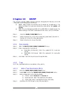
Page 44: ...Refer to Section 10 3 to set the ILMI 10 1 Community Step 1 Enter the MAIN CONF SNMP COMMUNITY menu Step 2 Enter a parameter in each field Read Only Community Enter the password for read only access R...

Page 45: ...ould be disabled first Follow the steps below to enable it Step 1 The default of ATM16 is disabled If it is enabled disable it from the MAIN QC ATM ATM16 menu Step 2 Enter the MAIN CONF SNMP ILMI menu...

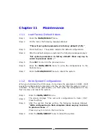
Page 46: ...the flash memory Step 7 Enter the MAIN REBOOT menu to reboot the system 11 2 Write System Configurations When you hold down the Ctrl S keys it only saves the parameters in RAM RAM keeps the configurat...

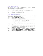
Page 47: ...Step 2 Enter a parameter in the following fields TFTP Server IP Address Enter the TFTP Server IP address File Name Enter the file name of the software TFTP option Choose Download Application Type Cho...

Page 48: ...parameters TFTP option Choose Upload Application Type Choose Configuration Step 3 Hold down the Ctrl S keys to start uploading the file to the TFTP server Step 4 When the upload is completed the syst...

Page 49: ...ompleted Press any key to continue Step 6 Enter the MAIN REBOOT menu to reboot the system Refer to Section 11 3 11 7 Homepage Upgrade The device utilizes the TFTP protocol to upgrade the homepage The...

Page 50: ...Monitor You can monitor the ADSL status from the MAIN MON STATUS menu Hardware status Software status Initialization status C ACT REQ Bit Rate Actual Bit Rate Max Indication to indicate if any of the...

Page 51: ...ion dB Current attenuation Noise margin dB Current noise margin Transmitted Blocks since reset the cumulative statistics of transmitted blocks since last reset Received Blocks since reset the cumulati...

Page 52: ...ce reset the received packets since last reset Received errors since reset the received errors since last reset The errors may be HEC error ABORT error Receive Length error LN CRC error CR Receive Fra...

Page 53: ...65 231 205 Step 3 You will be prompted to enter your user name and password To have full access privileges as an ADMINISTRATOR type root in the Login Name field If the default password was not changed...

Page 54: ...in menu 2 Setup Quick Setup 3 Config Basic Configuration 4 Advance Advance Configuration 5 Utility Utilities 6 Monitor Status Monitor The second area is the sub menu located on the left side that disp...

Page 55: ...n the table below are used during configuration Item Button Function 1 Next To go to the next step or page 2 Back To return to the previous page 3 Reset If the parameters are changed click this button...

Page 56: ...tup Wizard Figure 12 2 Quick Setup Step 2 Follow the five steps described in the Quick Setup Wizard Click the Next button when a step is completed and you will be prompted to complete the rest of the...

Page 57: ...on page allows you to load the factory default settings default IP 215 65 231 206 and baud rate 9600 bps or configure the other functions by following the online explanations Step 3 After the paramete...

Page 58: ...tep 2 Follow the online explanations to configure each function Step 3 After the parameters are set up the page will display all the adjusted settings for the administrator to review the settings Step...

Page 59: ...age ADI firmware Save and Restart 12 2 5 Monitor Click Monitor to access the Running Status Monitor page The following briefly describes the functions on the Monitor page System Information 1 System N...

Page 60: ...ABLED PROTOCOL ETHERNET IPCP STATIC ISP ISP1 NETWORK TYPE GLOBAL ATM VC VC1 IP ADDRESS SUBNET MASK VC VC1 VC16 VPI VCI 0 50 AAL5 ENCAPSULATIO N LLC VC QOS UBR PEAK CELL RATE 960000 SUSTAINABLE CELL RA...

Page 61: ...AL ATM VC VC IP ADDRESS 210 65 23 1 207 SUBNET MASK 255 255 2 55 0 ISP ISP1 8 ISP NAME USER NAME PASSWORD NAT PRIVATE POOL NUMBER POOL 1 START IP ADDRESS END IP ADDRESS GLOBAL POOL NUMBER POOL 1 START...

Page 62: ...E ANY SERVICE PORT NUMBER LIST PROTOCOL PRIVATE IP PRIVATE PORT SERVICE PORT INTERFACE DHCP GENERIC DHCP SERVER DISABLED DHCP START IP DHCP END IP DEFAULT GATEWAY SUBNET MASK DOMAIN NAME SERVER 1 DOMA...

Page 63: ...RATE BPS 960000 SUSTAINABLE CELL RATE BPS 0 BURST TOLERANCE MSEC 0 ROUTING STATIC ADD NETWORK HO ST ADDRESS SUBNET MASK GATEWAY ADDRESS METRIC DELETE NETWORK HO ST ADDRESS SUBNET MASK GATEWAY ADDRESS...

Page 64: ...ENABLED ADSL DOWNSTREAM FRAMING MODE 3 SCRAMBLE ENABLED ECHO CANCELATION ENABLED BIT SWAPPING ENABLED MON STATUS HW STATUS SW STATUS INIT STATUS C ACT REQ BIT RATE ACTUAL BIT RATE MAX INDICATION DS FR...

Page 65: ...RATE BPS RXRATE BPS STATUS UTIL TFTP TFTP SERVER IP ADDRESS FILE NAME TFTP OPTION DOWNLOA D APPLICATIO N TYPE FIRMWARE PING HOST IP ADDRESS DATA SIZE 32 TIMES 4 ROUTING TYPE NETWORK ADDRESS SUBNET MAS...

Page 66: ...65 QUIT...

Page 67: ...col over AAL5 RFC 1483 IP over AAL5 RFC 1483 VCs 16 AAL type AAL5 ATM service class UBR CBR VBR ATM UNI support UNI 3 1 PVC OAM F4 F5 Yes Management Item Specifications Console port RS232 DB9 SNMP Yes...

Page 68: ...P Yes Power supply Item Specifications Power source 110 VAC or 220 VAC 50 or 60 Hz Power consumption 6 0W Input voltage 12 to 14 VAC minimum 600 mA Environmental conditions Item Specifications Operati...

Page 69: ...t is not required to enter passwords when you access console But to access Telnet or Web you will be requested to enter password You can try the default passwords to log in Read write access ADMINISTR...

Reviews: