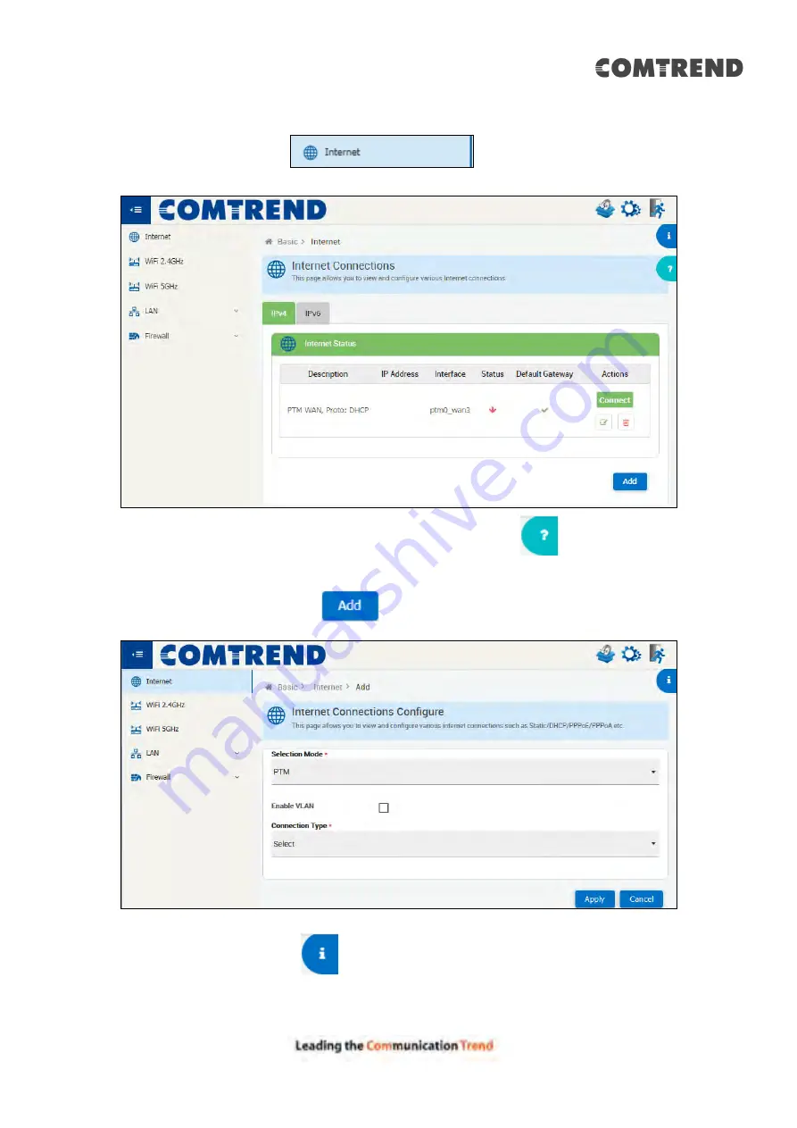
Comtrend Corporation 20190708 User Manual Download Page 22


21

4.1 Internet 

Click on the internet tab 

  to display the following. 


For a tour of the page, please click the question mark icon 

 on the upper 

right-hand side of this screen. 
 

To add aconnection, click the 

  button to display the following. 


Click the Information icon 

  on the upper right-hand side of this screen for 

information on Internet Connections. 
 

Summary of Contents for 20190708

Page 1: ...VR 3053 Home Gateway User Manual 261099 049 Version A1 0 June 14 2019...

Page 2: ...d adapter that are shipped with this device To safeguard the equipment against overheating make sure that all openings in the unit that offer exposure to air are not blocked Avoid using a telephone ot...

Page 3: ...o the RJ 11 jack Keep away from the fire For use in ventilated environment space Use 26 AWG or larger cable connect to RJ 11 port D branchez l alimentation lectrique avant l entretien Cet appareil est...

Page 4: ...r p is not more than that permitted for successful communication This device complies with Part 15 of the FCC Rules and Industry Canada licence exempt RSS standard s Operation is subject to the follo...

Page 5: ...ronnement non contr l Cet quipement doit tre install et utilis une distance minimum de 20 cm entre le radiateur et votre corps Cet metteur ne doit pas tre co localis es ou op rant en conjonction avec...

Page 6: ...Environment This symbol indicates that when the equipment has reached the end of its useful life it must be taken to a recycling centre and processed separate from domestic waste The cardboard box th...

Page 7: ...rol 28 CHAPTER 5 ADVANCED SETUP 30 5 1 DSL 31 5 1 1 Mode Setting 31 5 1 2 Status 32 5 1 3 ATM Channel 33 5 2 MULTIPLE BRIDGE 34 5 2 1 LAN VLAN 34 5 2 2 Bridges 34 5 3 MULTICAST 35 5 4 SYSTEM 36 5 4 1...

Page 8: ...5 10 2 URL Filter 81 5 11 OAM DIAGNOSTICS 82 5 11 1 ATM OAM F5 Loopback 82 5 12 NAT 83 5 12 1 DMZ 83 5 12 2 Port Mapping 84 5 12 3 Port Triggering 86 5 13 DEVICE MANAGEMENT 88 5 14 ROUTING 90 5 14 1...

Page 9: ...not only provides both ADSL and 35b VDSL but also integrated 5 Giga Ethernet ports and WLAN 802 11n 2 4GHz frequency band and 802 11ac 5GHz Frequency band Therefore VR 3053 is designed for high speed...

Page 10: ...r 2 Installation 2 1 Hardware Setup Non stackable This device is not stackable do not place units on top of each other otherwise damage could occur Follow the instructions below to complete the hardwa...

Page 11: ...WiFi connection ETH WAN PORT This port is designated to be used for Ethernet WAN functionality only Use 1000 BASE T RJ 45 cables to connect to Gigabit WAN server or 10 100BASE T RJ 45 cables for stan...

Page 12: ...o the ON position IN If the Power LED displays as expected then the device is ready for setup see section LED Indicators Caution 1 If the device fails to power up or it malfunctions first verify that...

Page 13: ...er the device has rebooted successfully the front panel should display as expected see section 2 1 3 Front Panel for details NOTE If pressed down for more than 60 seconds the VR 3053 will go into a fi...

Page 14: ...the light will remain blue The light will turn red when it attempts to reconnect and DHCP or PPPoE fails Off Modem power off modem in bridged mode or WAN connection not present Blink IP connected and...

Page 15: ...ff The device is powered down Red On POST Power On Self Test failure or other malfunction A malfunction is any error of internal sequence or state that will prevent the device from connecting to the D...

Page 16: ...ccess enabled Technical Note During power on the device initializes all settings to default values It will then read the configuration profile from the permanent storage section of flash memory The de...

Page 17: ...nvolved are similar for most operating systems OS Check your OS support documentation for further details STEP 1 From the Network Connections window open Local Area Connection You may also access this...

Page 18: ...your OS support documentation for further details STEP 1 From the Network Connections window open Local Area Connection You may also access this screen by double clicking the Local Area Connection ico...

Page 19: ...s for the device in the Web address field For example if the default IP address is 192 168 1 1 type http 192 168 1 1 NOTE For local administration i e LAN access the PC running the browser must be att...

Page 20: ...19 STEP 3 After successfully logging in for the first time you will reach this screen You can also reach this page by clicking on the following icon located at the top of the screen...

Page 21: ...nu has several options and selecting each of these options opens a submenu with more selections NOTE The menu items shown are based upon the configured connection s and user account privileges For exa...

Page 22: ...a tour of the page please click the question mark icon on the upper right hand side of this screen To add aconnection click the button to display the following Click the Information icon on the upper...

Page 23: ...22 IPv6 for your reference...

Page 24: ...he main wireless LAN interface that operates in the 2 4GHz range It offers greater coverage and supports legacy devices Click the Information icon on the upper right hand side of this screen for infor...

Page 25: ...wireless LAN interface that operates in the 5GHz range It offers less interference and is ideal for media streaming and gaming Click the Information icon on the upper right hand side of this screen fo...

Page 26: ...ovide IP address to devices connected on the LAN side of the CPE Applicable for all wired and wireless devices that requests a dynamic IP address Click the Information icon on the upper right hand sid...

Page 27: ...the LAN Side of the CPE MAC Address MAC address of the device that is connected to the LAN port Host Name Host Name of the device that is connected to the LAN port IP Address IP Address of the device...

Page 28: ...de array of common hacker attacks This is done by restricting connection parameters to limit the risk of intrusion Application layer protocol services can be enabled disabled from this page Click the...

Page 29: ...tal Control Access to the internet from LAN Host PCs can be controlled based on MAC addresses and Time of Day Select the default action Permit or Deny and click the button Click the button to display...

Page 30: ...29 Click the Information icon on the upper right hand side of this screen for information on Parental Control Rules Click the button to save your Parental Control Rules...

Page 31: ...following icon located at the top of the screen The web user interface window is divided into two frames the main menu at left and the display screen on the right The main menu has several options an...

Page 32: ...Line offers WAN DSL Connectivity on various DSL Modes Provides configuration for xDSL modes various annex modes and upstream and downstream attributes Click the Information icon on the upper right han...

Page 33: ...32 5 1 2 Status Provides the various status and statistics information...

Page 34: ...channels on which Internet connections are configured VPI VCI The Identifier of the Virtual Path and the Virtual Channel for the ATM Encapsulation The encapsulation types are LLC and VCMUX Link Type T...

Page 35: ...nformation icon on the upper right hand side of this screen for information on the LAN VLAN Settings 5 2 2 Bridges Displays Bridge Interfaces Click the Information icon on the upper right hand side of...

Page 36: ...35 5 3 Multicast This page allows you to configure the Multicast services Click the Information icon on the upper right hand side of this screen for information on Multicast Settings...

Page 37: ...llows users to take configuration backup restore to previous configuration or to factory settings upgrade firmware and reboot device Click the Information icon on the upper right hand side of this scr...

Page 38: ...37 5 4 2 User Management Configure new users with add delete and modify options Click the button to display the following...

Page 39: ...screen for information on User Management Settings 5 4 3 System Time Configuration to enable the device to synchronize the system time with the time servers Click the Information icon on the upper rig...

Page 40: ...39 5 4 4 System Log The CPE device provides customized logging the messages to File Remote Click the Information icon on the upper right hand side of this screen for information on System Log Settings...

Page 41: ...stics Allows diagnosis to be performed on various sub systems of the CPE Click the button to restart the diagnostic tests Input the IP Host address and click the button start the test See below for pi...

Page 42: ...41 Input the url and click the button start the test See below for trace route result...

Page 43: ...42 5 5 Dynamic DNS Dynamic DNS allows the user to update wan IP address with one or many dynamic DNS services So anyone can access services on computer using DNS like address...

Page 44: ...43 Client Settings Click the button to display the following Click the Information icon on the upper right hand side of this screen for information on Client Settings...

Page 45: ...44 Supported Servers Click the button to display the following Click the Information icon on the upper right hand side of this screen for information on Server Settings...

Page 46: ...iFi 2 4GHz 5 6 1 Advanced Advanced settings for the wireless LAN interfaces that operate in the 2 4GHz range Typically you shouldn t need to change these settings The settings shown above are describe...

Page 47: ...lt Power Scale 12 25 50 100 and 100 by default Explicit Beamforming Turned on by default Implicit Beamforming Turned on by default LDPC Turned on by default STBC Turned on by default Number of Antenna...

Page 48: ...low guest access to the internet while preventing guests from connecting to your main network Click the button to display the following The settings shown above are described below SSID 2 4G SSID Secu...

Page 49: ...ttings shown above are described below Rekey Interval 3600 seconds by default Passphrase The password AP Isolation Enable Disable AP isolation Max Connected STAs The maximum number of STAs that can be...

Page 50: ...h WPS Click the button to reset WPS to Unconfigured mode Click the button then press the WPS pushbutton on the device you want to connect within two minutes To connect a new device by PIN Personal Ide...

Page 51: ...50 To add this device to a network enter the PIN in the box on the managing device To create a new PIN Click the button...

Page 52: ...s to connect based on their MAC address The settings shown above are described below SSID 2 4G SSID ACL Mode Select the access control list mode from the drop down menu To add a filter click the butto...

Page 53: ...bution System The settings shown above are described below SSID 2 4G Wi Fi SSID WDS Mode WDS mode setting Disabled Legacy Just support 802 11g with WEP Hybrid Support both AP and WDS functions Click t...

Page 54: ...53 5 6 6 Statistics Displays WLAN statistics of the access point and connected devices The settings shown above are described below SSID 2 4G Wi Fi SSID...

Page 55: ...ed Bytes Sent Number of Bytes Sent Discard Packets Received Number of Discard Packets Received Discard Packets Sent Number of Discard Packets Sent Errors Received Number of Errors Received Packets not...

Page 56: ...55 5 6 7 Airtime Fairness Check the checkbox to display the following Click the button to enable airtime fairness for varied wireless clients...

Page 57: ...ted Each STA or SSID VAP has a predefined weight in of the total airtime Weights can be Per AC Access Category Per STA Per SSID Per SSID then per STA ATM Interval msecs This is basic time frame in mil...

Page 58: ...Airtime Fairness Check the checkbox to display the following Click the button to add an entry Then click the icon to edit the entry Click the button to apply your changes If required click the icon to...

Page 59: ...WiFi 5GHz 5 7 1 Advanced Advanced settings for the wireless LAN interfaces that operate in the 2 4GHz range Typically you shouldn t need to change these settings The settings shown above are described...

Page 60: ...lt Power Scale 12 25 50 100 and 100 by default Explicit Beamforming Turned on by default Implicit Beamforming Turned on by default LDPC Turned on by default STBC Turned on by default Number of Antenna...

Page 61: ...s to the internet while preventing guests from connecting to your main network Click the button to display the following The settings shown above are described below SSID 2 4G SSID Security Type Selec...

Page 62: ...are described below Rekey Interval 3600 seconds by default Passphrase The password AP Isolation Enable Disable AP isolation Max Connected STAs The maximum number of STAs that can be connected WMM PS...

Page 63: ...h WPS Click the button to reset WPS to Unconfigured mode Click the button then press the WPS pushbutton on the device you want to connect within two minutes To connect a new device by PIN Personal Ide...

Page 64: ...63 To add this device to a network enter the PIN in the box on the managing device To create a new PIN Click the button...

Page 65: ...igurations to block devices from connecting or allow devices to connect based on their MAC address The settings shown above are described below SSID 2 4G SSID ACL Mode Select the access control list m...

Page 66: ...65 To add a filter click the button to display the following Input the MAC address and click the or box to allow or deny...

Page 67: ...bution System The settings shown above are described below SSID 2 4G Wi Fi SSID WDS Mode WDS mode setting Disabled Legacy Just support 802 11g with WEP Hybrid Support both AP and WDS functions Click t...

Page 68: ...67 5 7 6 Statistics Displays WLAN statistics of the access point and connected devices The settings shown above are described below SSID 5G Wi Fi SSID...

Page 69: ...ed Bytes Sent Number of Bytes Sent Discard Packets Received Number of Discard Packets Received Discard Packets Sent Number of Discard Packets Sent Errors Received Number of Errors Received Packets not...

Page 70: ...69 5 7 7 Airtime Fairness Check the checkbox to display the following Click the button to enable airtime fairness for varied wireless clients...

Page 71: ...ted Each STA or SSID VAP has a predefined weight in of the total airtime Weights can be Per AC Access Category Per STA Per SSID Per SSID then per STA ATM Interval msecs This is basic time frame in mil...

Page 72: ...Airtime Fairness Check the checkbox to display the following Click the button to add an entry Then click the icon to edit the entry Click the button to apply your changes If required click the icon to...

Page 73: ...72 5 8 UPnP Click the radio button to to enable UPnP protocol and then click the button to save your choice Click the button to refresh the screen...

Page 74: ...rvice Quality of Service QoS settings enables you to manage and optimize the performance of the applications It shapes the network traffic and prioritizes the devices and services by controlling the b...

Page 75: ...settings enables you to manage and optimize the performance of the applications Select Ingress or Egress from each of the drop down menus LAN WLAN DSL WAN and Eth WAN Click the button to see more deta...

Page 76: ...o edit the entry If required click the icon to delete an entry Click the button to display the following Click the Information icon on the upper right hand side of this screen for information on Queue...

Page 77: ...76 Click the button to display the following Click the Information icon on the upper right hand side of this screen for information on Classifier Settings...

Page 78: ...77 5 9 2 QoS Graphs This function is not supported on this firmware release...

Page 79: ...78 5 9 3 Queue Stats Shows the statistics of configured queues Click the Information icon on the upper right hand side of this screen for information on Quque Statistics info...

Page 80: ...sly Incorrect configuration may render device inaccessible 5 10 1 Packet Filter By enabling Packet filter traffic can be passed or blocked at a network interface based on source and destination addres...

Page 81: ...80 Click the Information icon on the upper right hand side of this screen for information on Packet Filter settings...

Page 82: ...81 5 10 2 URL Filter This page allows the user to configure URL Filter feature Click the Information icon on the upper right hand side of this screen for information on Packet Filter settings...

Page 83: ...OAM Diagnostics This page allows user to Test OAM 5 11 1 ATM OAM F5 Loopback Click the Information icon on the upper right hand side of this screen for information on ATM OAM F5 Loopback Diagnostic r...

Page 84: ...e user to view and configure the virtual DMZ Host Such a configuration opens up the specified host to unrestricted two way Internet access Click the Information icon on the upper right hand side of th...

Page 85: ...5 12 2 Port Mapping Configure a rule to allow remote computers for example computers on the Internet to connect to a specific computer or service within a LAN Click the button to display the followin...

Page 86: ...85 Click the Information icon on the upper right hand side of this screen for information on Port Mapping settings...

Page 87: ...86 5 12 3 Port Triggering Port triggering opens an incoming port when the user s computer is using a specified outgoing port trigger for specific traffic Click the button to display the following...

Page 88: ...87 Click the Information icon on the upper right hand side of this screen for information on Port Trigger settings...

Page 89: ...88 5 13 Device Management The settings shown above are described below...

Page 90: ...min by default Periodic Inform Enable Periodic Inform Enable Periodic Inform Interval 300 seconds by default Periodic Inform Time Periodic Inform Time CWMP Retry Minimum Wait Interval 5 seconds as def...

Page 91: ...90 5 14 Routing Web Page to Add Delete Static Route in the System 5 14 1 Static Routing Click the first button to display the following IPv4 Static Route...

Page 92: ...e described below Heading Description Destination IP Address Destination Server or Gateway IP Destination Subnetmask 255 255 x x Gateway IP Address 192 168 1 x Interface Interface connect to Destinati...

Page 93: ...92 Click the second button to display the following IPv6 Static Route...

Page 94: ...93 The settings shown above are described below Heading Description Destination IP Prefix EX 2001 DB8 3000 0 16 NextHop EX 2001 DB8 1 1 Interface EX Ethernet1 0...

Page 95: ...14 2 RIP This page allows to enable or disable RIP and set mode of operation Click the Information icon on the upper right hand side of this screen for information on Routing Information Protocol sett...

Page 96: ...95 Chapter 6 Logout To log out from the device simply click the following icon located at the top of your screen Upon successful exit the following message will be displayed...

Page 97: ...Adaptation UPBO Upstream Power Back off Ethernet IEEE 802 3 IEEE 802 3u IEEE 802 3ab 10 100 1000 BASE T auto sense Support MDI MDX Networking Protocols RFC 2364 PPPoA RFC 2684 RFC 1483 Bridge Router R...

Page 98: ...E 802 11n 2 4GHz 2T2R Backward compatible with 802 11g b 2412 2462 MHz IEEE 802 11ac 5GHz 2T2R Backward compatible with 802 11n a U NII 1 5150 5250 MHz U NII 3 5725 5825 MHz WPA WPA PSK WPA2 WPA2 PSK...

Page 99: ...st enable SSH access for the LAN or WAN from the Management Access Control Services menu in the web user interface To access the router using the Linux ssh client For LAN access type ssh l root 192 16...

Reviews: